Do you have a question about the Keysight Technologies N6700 and is the answer not in the manual?
Details terms and limitations of the product warranty.
Information on manual part numbers, print dates, and compliance.
Information on WEEE compliance, product certification, and remedies.
Support details, licensing, US government rights, and trademarks.
Essential safety rules for instrument operation.
Detailed warnings for specific operational hazards.
Explains standard safety symbols used in the manual.
Outlines the manual's chapters and their core content.
Provides contact information for warranty, service, and support.
Information on obtaining the latest manual and firmware versions.
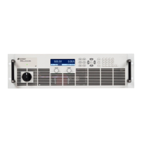
Introduces the N6700 system and details model variations.
Describes the layout and components of the front and rear panels.
Details the front panel display modes and key functions.
Explains the functionality of each front panel key.
Provides a reference for navigating the front panel menu system.
Lists available SCPI commands for instrument control.
Details mainframe models, options, and supplied accessories.
Guides on unit inspection and initial installation procedures.
Instructions for installing power modules into the mainframe.
Procedures for mounting the unit in a rack or on a bench.
Instructions for connecting the line cord, output terminals, and wires.
Guidance on wire sizes, SMU wiring, and load impedance.
Describes how to connect outputs in parallel, series, or groups.
Explains remote sensing and factors affecting load connections.
Details the connection and use of the auxiliary voltage input.
Guides on initial power-up and setting basic output parameters.
Explains how to use the front panel menu for configuration.
Instructions for connecting and configuring the instrument's interfaces.
Describes Web server, Telnet, and socket communication.
Covers interface security, password protection, and factory settings.
Details setting voltage, current, mode, slew rate, and enabling output.
Guides on timing output changes with triggers.
Explains creating sequences of voltage/current changes.
Covers measurement ranges, seamless autoranging, and simultaneous measurements.
Describes advanced measurement capabilities like sample rate and windowing.
Explains over-voltage, over-current, and other protection features.
Guides on logging measurements externally.
Covers self-tests, instrument identification, and state storage.
Lists key specifications for N6700B, N6701A, N6702A mainframes.
Details environmental, electrical, and physical characteristics.
Introduces the digital port and its pin functions.
Details setup for digital I/O, triggers, faults, and inhibit.
Explains daisy-chaining fault/inhibit signals for system protection.
Procedures for clearing protection faults and managing output state.
Explains mainframe and module power limits.
Guides on programming module power limits.
Details minimum delay offsets and user-programmed delays.
Guides on synchronizing turn-on sequences across multiple units.
Explains how synchronized outputs behave.
Describes constant voltage and constant current operating modes.
Explains voltage and current priority modes for SMUs.
| Model | N6700 |
|---|---|
| Type | Modular Power System |
| Output Channels | Up to 4 |
| Power Rating (per module) | Up to 300W |
| Output Voltage Range | Depends on module (e.g., 0-20V, 0-50V) |
| Output Current Range | Depends on module (e.g., 0-10A) |
| Output Power | Varies by module |
| DC Voltage | Depends on module |
| DC Current | Depends on module |
| Interface | GPIB, LAN, USB |
| Display | Graphical LCD |