2 Installation
40 Keysight N6700 User’s Guide
Series Connections
Floating voltages must not exceed 240 VDC. No
output terminal may be more than 240 VDC from chassis ground.
Only connect outputs that have identical voltage and current ratings in
series. Keysight Models N678xA SMU and N6783A–x cannot be
connected in series.
To prevent currents from damaging the power system when the load is
connected, always turn series-connected outputs on and off together.
Do not leave one output on while the other is off.
Connecting outputs in series provides a greater voltage capability than
can be obtained from a single output. Because the current is the same
through each element in a series circuit, outputs connected in series
must have equivalent current ratings.
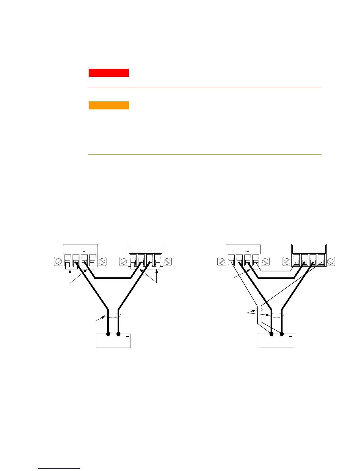
The following figures show how to connect two outputs in series to a
single load. If voltage drop in the load leads is a concern, connect the
sense leads of output 1 and output 2 for remote sensing as shown in the
figure on the right. Note that the +sense lead of output 1 must remain
connected to the -sense terminal of output 2.
The following figure shows the connections for 50A power modules.
OUTPUT 2
OUTPUT 1
+S + -S
+S + -S
WITH REMOTE SENSING
SENSE
JUMPER
INSTALLED
OUTPUT 2 OUTPUT 1
+S + -S
TWIST LEADS
LOAD
+S + -S
WITH LOCAL SENSING
+
TWIST LEADS
SENSE
JUMPERS
INSTALLED
SENSE
JUMPERS
INSTALLED
LOAD
+