3 Operating Instructions
28 Keysight 11683A Operating and Service Manual
Operation of the Controls
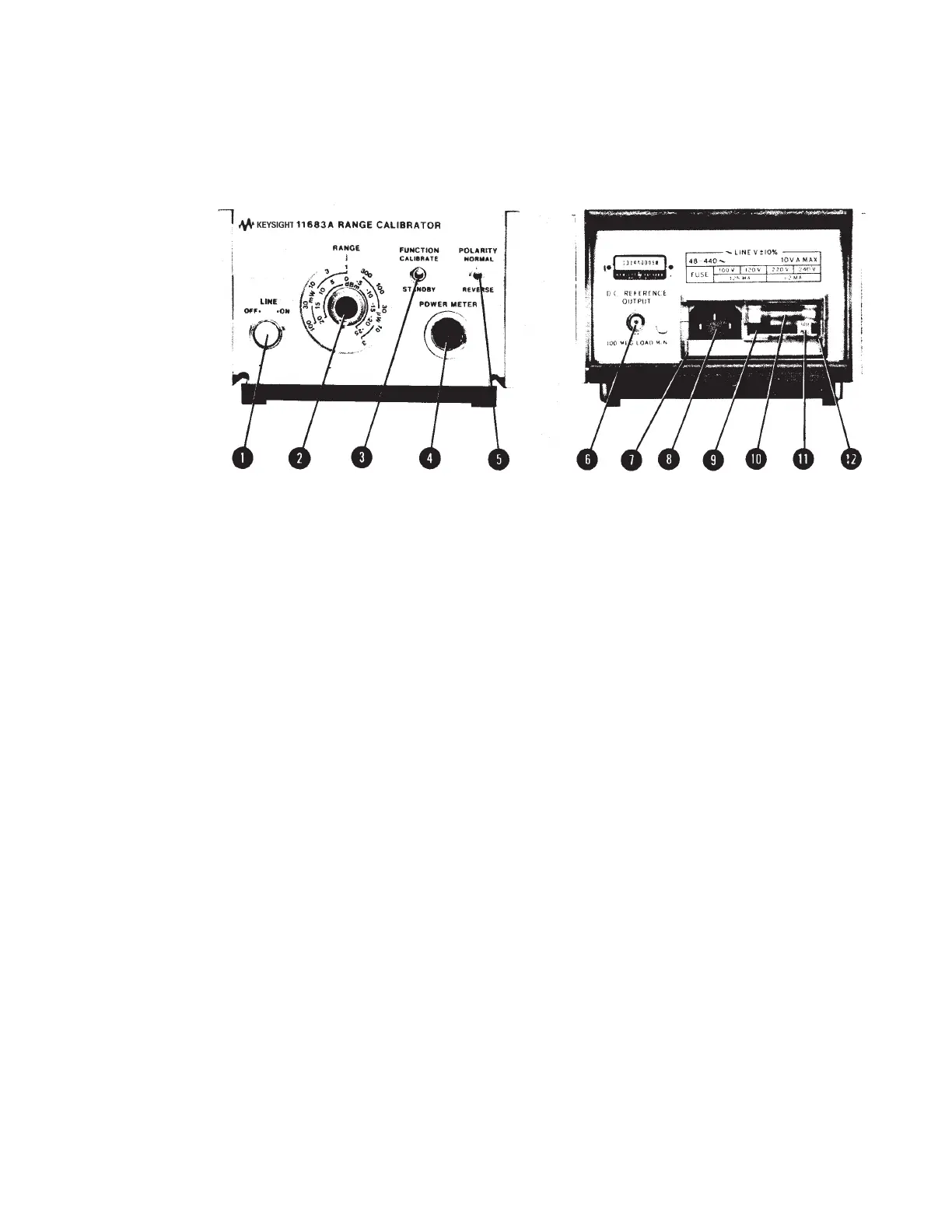
Operation of the controls of the 11683A is explained in Figure 3-1.
Figure 3-1 Front and rear panel features (illustrations for indication only)
1LINE switch. Controls primary power. Illuminated when instrument is ON.
2RANGE switch. Equivalent to compatible Power Meter's Range Switch; produces a full scale
Power Meter reading when 11683A and Power Meter Range switches are set to same scale.
3FUNCTION switch. When the switch is set to CALIBRATE an output dependent on the RANGE
switch setting is coupled to the Power Meter. In STANDBY mode the output is grounded.
4 POWER METER connector. Connects the output to, and control signals from, compatible
Power Meter via Power Sensor Cable.
5 POLARITY switch. An upscale reading is obtained on the Power Meter when the switch is set to
NORMAL. The REVERSE setting produces a downscale reading.
6 D.C. REFERENCE OUTPUT connector. DC reference voltage output from RANGE
Switch. Load resistance must be ≥ 100 MΩ for proper operation of the 11683A.
7 Power Mod ule Assembly.
8Receptacle. Couples transformer primary to line voltage via power cable.
9 Line Voltage Selection Card. Matches transformer primary to line voltage. Refer to Figure 2-1.
10 Fuse. A 1/8 A fuse is used at 100/120 Vac; 1/16 A fuse at 230/240 Vac.
11 Fuse Pull Handle. Mechanical interlock; fuse must be removed before extraction of Line Voltage
Selection Card.
12 Window. Safety interlock; fuse cannot be removed while power cable is coupled to Power
Module Receptacle.