Service 6
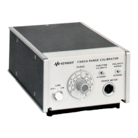
Keysight 11683A Operating and Service Manual 45
Principles of Operation
The principles of operation are intended to give the user a basic understanding of circuit operation
and is, therefore, the most important troubleshooting aid available.
Power supply
The A4 Power Module Assembly contains the Line Voltage Selector Card which matches the line
voltage to power transformer primary. A line filter reduces line surge and transients.
The A2 Power Supply Assembly contains a bridge rectifier A2CR1-4, filter capacitor A2C1, a
packaged voltage regulator circuit A2U1, and its associated components.
Within the IC package is a reference voltage generator, an operation amplifier, regulator driver,
series regulator, and current limiting transistors. The reference voltage output, pin 4, is coupled to
the non-inverting operational amplifier input, pin 3. The amplifier output drives the regulator driver
and series regulator transistors and the regulated output is coupled from the emitter, through the
current sense resistor A2R2, to the POLARITY switch A2S1. A2R3, R1, and R4 form a voltage
divider through which the feedback bias is coupled to A2U1 pin 2, the inverting input.
If the current flow through A2R2 exceeds 20 mA, the current limiting transistor is turned-on and
the drive voltage to the regulator driver is reduced which drops the regulated voltage toward zero.
A2C2 provides high frequency rolloff which reduces the feedback loop tendency to support
spurious oscillations.
A1 range switch assembly
The Range switch is a voltage divider which changes the output voltage by a factor of
approximately √10 for each sequential range change.
A3 sampling gate assembly
The dc input from the Range Switch assembly is divided by one thousand and is coupled to the
A3A1U1 Sampling Gate circuit. A 220 Hz square wave drive signal from the Power Meter is coupled
to the FET gates. When A3A1U1Q1 is conducting, the dc input is coupled to the Input Amplifier
A3A1Ql. When A3A1U1A2 is conducting, the input to the amplifier is essentially ground. The signal
coupled to the Input Amplifier is 220 Hz ac, with the amplitude directly proportional to the dc input
level.
The Input Amplifier and the first amplifier in the Power Meter are the component parts of a Hybrid
Operational Amplifier. The Amplifier, which has a gain of approximately 730, is shown in Figure 6-2.