6Service
46 Keysight 11683A Operating and Service Manual
Troubleshooting
The troubleshooting information is intended to supplement the principles of operation and
schematics. This information should reduce troubleshooting time and increase the ease of solving
problems that do not have obvious answers.
Power supplies
If the output noise level has increased and the dc voltage at A2U1 pin 8 has decreased slightly, one
of the bridge rectifier diodes or A2C1 may be defective.
If the output voltage has decreased, 0.6 Vdc measured across A2R2 indicates the current limiter is
operating.
Measure the voltage on A2U1 pins 2 and 3. If the voltage difference is >10 mVdc, verify that the
regulated output has correctly followed the change in input levels. The regulated output's relative
change from normal should follow the non inverting input change and be opposite to the
inverting input change. If the preceding statement is not true, the integrated circuit is probably
defective, otherwise, the problem is probably with the associated components of A2U1.
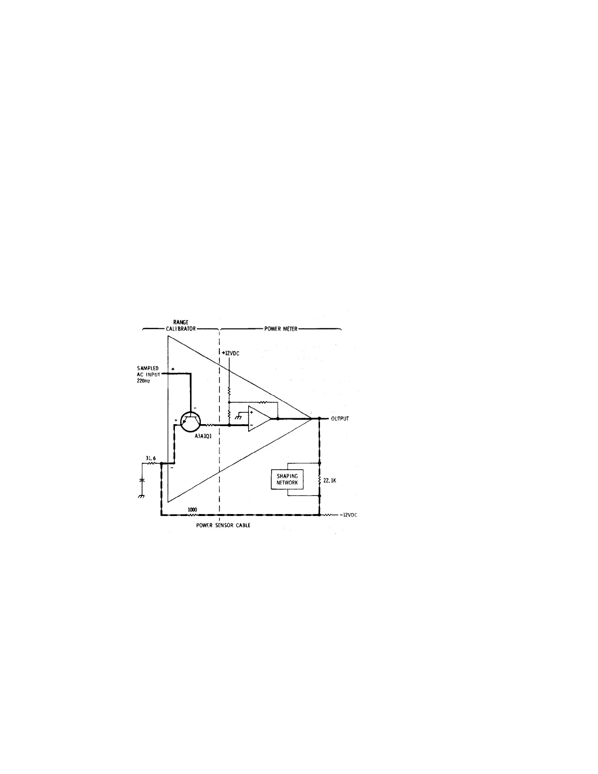
Figure 6-2 Hybrid operational amplifier
A1 range switch assembly
Voltages and/or, resistance measurements, taken while performing the Range Switch Performance
Test, may be out of the specified tolerances. This may be due to a definite change-in-resistance of
one of the resistors mounted on the switch, high resistance contacts on the FUNCTION or RANGE
switches, or a soldered connection which exhibits high resistance.