6Service
44 Keysight 11683A Operating and Service Manual
FET assembly removal
1 Remove the A3A1 Circuit Board Assembly. Refer to “Disassembly of A3 sampling gate
assembly” on page 43.
2 Remove the 0-80 x 0.500" cap screw, spring, clamp, and A3R1.
3 Remove the RTV
[1]
coating which covers the FET pin connections to the printed circuit board.
4 With a desoldering tool, remove the solder from the six pins which hold the FET Assembly in
place.
5 Carefully break each pin loose from the printed circuit board with a soldering aid tool.
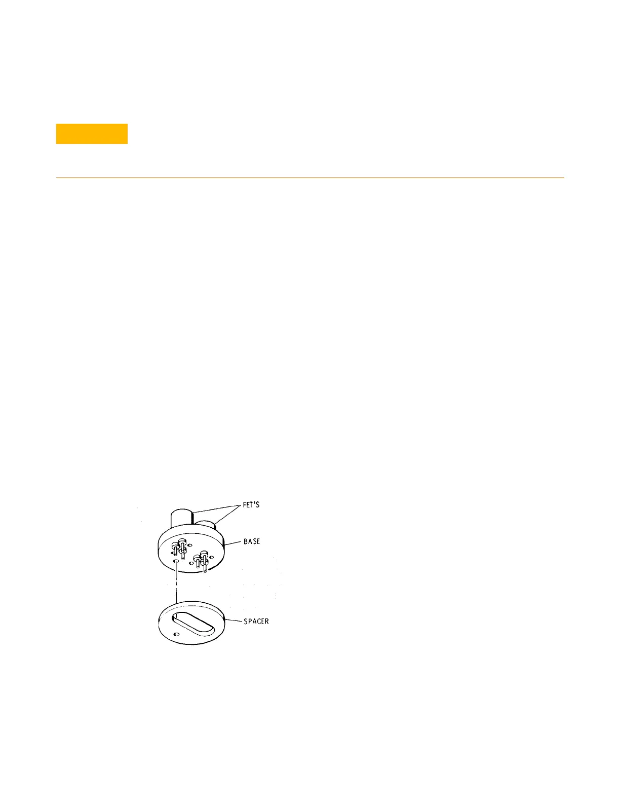
6 Gently lift the FET Assembly and spacer from the circuit board. Refer to Figure 6-2.
FET assembly installation
1 Insert the FET Assembly leads through the spacer and printed circuit board. Refer to Figure 6-1.
2 Insert the clamp and cap screw to hold the spacer and assembly in place against the printed
circuit boards.
3 Quickly solder the FET leads to the circuit board.
4 With hypodermic needle place RTV
[1]
into the hollow portion of the spacer. For this purpose the
needle is inserted into the hole in the circuit board directly beneath the FET Assembly.
5 Cover the soldered connections from the FET Assembly with RTV
[1]
.
6 Cover the rest of the circuit side of the A2 assembly circuit board with Krylon
[2]
.
Figure 6-1 FET assembly and spacer
Excessive heat from the soldering iron when installing or removing the assembly may
destroy the FET internal circuitry. Before removing the FET Assembly be sure that it must be
replaced. The Troubleshooting information gives the correct procedures for verifying that
the FET's are defective.
[1] RTV - 732 RTV Silicone Rubber Adhesive/Sealant by Dow Corning Corp., Midland, Michigan, 48640.
[2] Krylon- No. 1302 Humiseal Protective Coating, Type 1B12 by Columbia Technical Corp., Woodside 77, New York.
Krylon Inc., Norristown, Pennsylvania