Keysight N9927-90001 User’s Guide 373
VVM (Vector Voltmeter) Mode - Option 308
Overview
Overview
In the FieldFox, both 1-port and 2-port measurement types use a different
configuration setup from the HP/Keysight 8508A Vector Voltmeter.
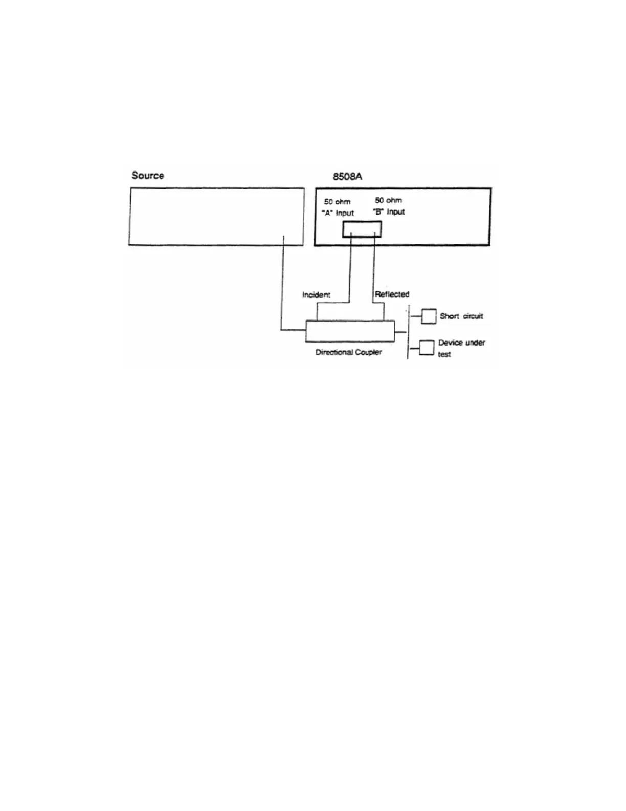
Figure 20-2 Typical 8508A measurement configuration –as shown in the 8508A manual.
The above block diagram requires an external source and directional coupler to
measure the electrical length of a DUT or cable to be trimmed. Separate paths
are used to measure the Incident signal (A) and Reflected signal (B). To
measure the ratio of the Reflected/Incident signals, you were required to select
B/A for both the Magnitude and Phase display.
In the FieldFox, the source and directional coupler are inside the instrument.
This allows you to connect the DUT to ONLY the FieldFox PORT 1, with NO
external instruments, in order to make Cable Trimming measurements.
See the FieldFox block diagram and Cable Trimming procedures beginning in
“1-Port Cable Trimming Measurements ” on page 379.