Do you have a question about the Keysight E4980A and is the answer not in the manual?
Procedures for verifying the condition of the LCR meter and its accessories after unpacking.
Steps to ensure the power supply and fuse are correctly set up and the power cable is properly connected.
Describes the setup for a static-safe workstation to protect electronic components from ESD damage.
Explains the procedure for turning the instrument power ON and OFF and confirming its status.
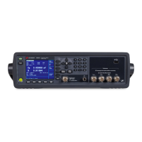
Identifies and explains the function of each part on the instrument's front panel.
Describes the MEAS DISPLAY page where measurement controls and settings are configured.
Explains the internal DC bias feature, how to enable it, and its output range.
Describes the four default states the instrument can be initialized into for configuration.
Details how to configure measurement controls accessible via the MEAS SETUP page.
Describes the four trigger modes (INT, EXT, MAN, BUS) supported by the instrument.
Explains the ALC feature for adjusting voltage/current across the DUT to a set level.
Explains the feature useful for testing varactor diodes by controlling DC bias polarity.
Describes how to display deviation values instead of actual measurements using absolute or percentage modes.
Explains how to perform Open/Short/Load correction to compensate for errors.
Details how to compensate for stray admittances using the open correction feature.
Explains how to compensate for residual impedances using the short correction feature.
Explains how to configure the instrument's built-in comparator for bin sorting.
Explains how to enable or disable the instrument's built-in comparator.
Describes how to configure automatic sweep measurements by sweeping frequency, signal level, DC bias, or DC source.
Explains the two sweep modes: sequential (SEQ) and step (STEP).
Displays system information and allows configuration of handler and scanner interfaces.
Explains how to interact with a handler using the 36-contact Amphenol connector.
Describes the interface for connecting a scanner to perform multi-channel correction.
Details how to configure GPIB interface, LAN status, beep features, and system date.
Details how to configure the GPIB address for controlling the instrument from an external controller.
Explains how to configure the IP address for LAN communication, either automatically or manually.
Describes how to check the instrument's behavior for maintenance and repair purposes.
Information on saving and recalling configurations and measurement results via internal or USB memory.
Explains how to save and recall instrument configuration states to internal memory or USB memory.
Provides steps for saving and recalling instrument configurations to/from internal memory registers.
Details how to save and recall instrument configuration states to/from USB memory.
Describes how to save measurement results obtained by the instrument into USB memory as .CSV files.
Outlines the fundamental steps for measuring impedance of capacitors, inductors, and resistors.
Describes the 4TP configuration used to improve measurement accuracy by avoiding mutual inductance and residual factors.
Details correction functions like Cable Length, OPEN, SHORT, and LOAD to compensate for test fixture and lead errors.
Describes a practical measurement example using the DC source with list sweep.
Explains GPIB as an interface standard for connecting computers and peripherals for instrument control.
Details controlling the instrument via a LAN using SICL-LAN or telnet server.
Explains controlling the instrument through a Web server using Internet Explorer.
Describes device control via USB, equivalent to GPIB control, using USBTMC protocol.
Details the trigger system responsible for measurement cycle start and system state control.
Explains the data buffer memory function for holding measurement results and their transfer.
Describes configuring the instrument for automatic continuous measurement and starting measurement on demand.
Explains how to trigger the instrument to start measurement when the system is in the 'Waiting for Trigger' state.
Explains how to detect the end of measurement using status registers and SRQ.
Describes the status byte register, its bit assignments, and how it indicates instrument status.
Details an application program to set measurement conditions and LCD display, including VISA functions.
Explains an application program for saving and recalling instrument status data from internal flash memory.
Lists and describes commands specific to the E4980A/AL, covering measurement functions and system settings.
Lists essential precautions for operating the E4980A/AL safely and correctly.
Describes the daily checks required, including self-tests at power-on and from the front panel.
Lists common issues and checks to perform when the instrument is not functioning correctly.
Troubleshooting steps for when the instrument fails to power on or display anything.
Guidance for troubleshooting when the instrument enters Service Mode after failing power-on or self-test.
Troubleshoots issues with abnormal measured values, suggesting re-measuring compensation data or checking MULTI compensation settings.
Directs users to the Error Messages section for information on interpreting and resolving error or warning messages.
Lists checks for troubleshooting when the instrument does not respond to or malfunctions with an external controller.
Provides an alphabetical listing and description of error messages to indicate the instrument's operating status.
Lists warning messages displayed in the instrument status area, indicating conditions like ALC unable to regulate or signal source overload.
Explains signal definitions for test result and control signals when using the handler interface with the comparator.
Details signal definitions for list sweep comparator, differing from the standard comparator.
Provides detailed instructions for setting up the handler interface board, including jumpers and bit switches.
Offers information necessary to operate the E4980A/AL using the scanner interface.
Explains how to make the scanner interface valid for multi-channel correction and I/O signals.
Details performing OPEN, SHORT, and LOAD data measurements for each scanner channel.
Provides information on using Option 301 Scanner Interface for multi-channel correction and timing synchronization.
Provides instructions for setting up the scanner interface board, including bit switch settings.
| Frequency Range | 20 Hz to 2 MHz |
|---|---|
| Basic Accuracy | 0.05% |
| DC Bias Voltage | 0 V to ±40 V |
| Measurement Functions | L, C, R, Z, D, Q |
| DC Bias Current | 0 A to 20 mA (using external DC bias source) |
| Display | LCD |
| Interface | LAN, USB, GPIB |
| Dimensions | 426 mm (W) x 177 mm (H) |
| Weight | 13.5 kg |


