Keysight E4980A/AL Precision LCR Meter 195
Measurement Procedure and Examples
Four-Terminal Pair Configuration
Four-Terminal Pair Configuration
Generally, any mutual inductance, interference of the test signals, or unwanted
residual factors in the connection method incidental to ordinary termination
methods will have a significant effect on measurement, especially at high
frequency. The E4980A/AL employs a four-terminal pair measurement
configuration that permits easy, stable, and accurate measurement while
avoiding the negative influences inherent in the above factors. The 4TP
configuration can improve the impedance measurement range to below 1 m
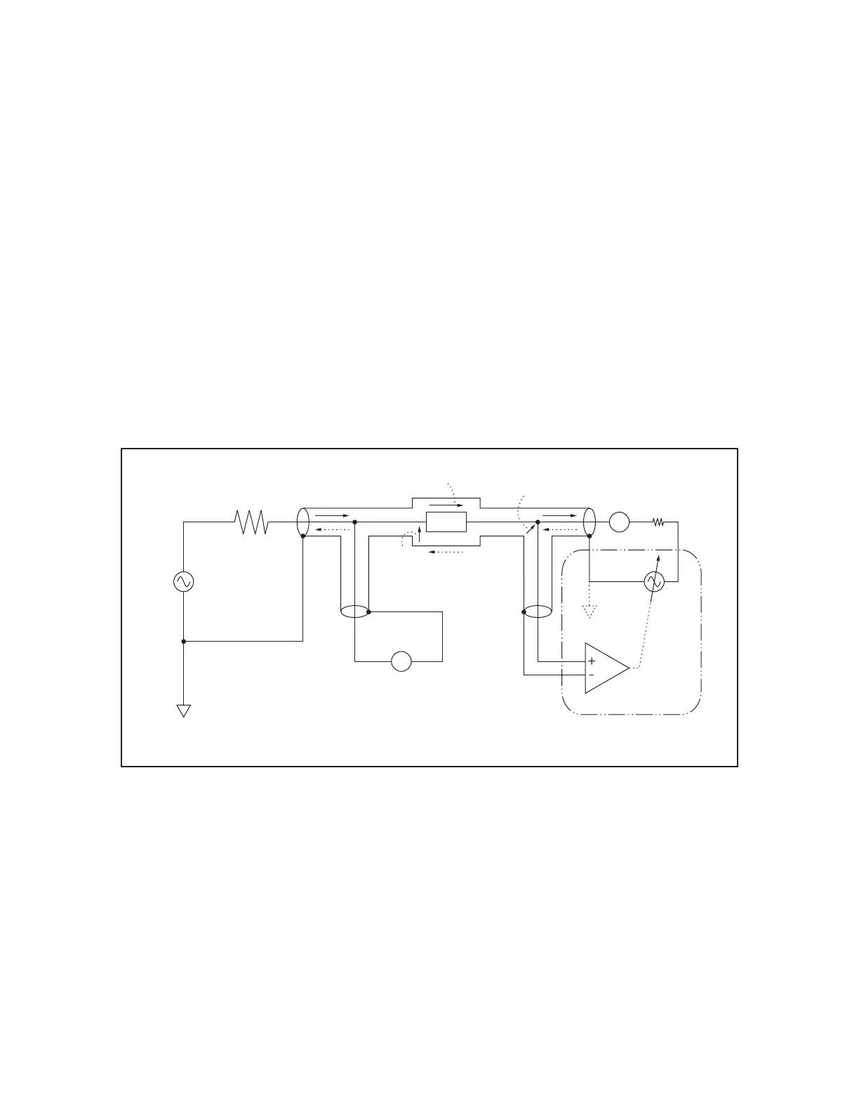
Figure 7-7 shows the four-terminal pair measurement principle. The set of
UNKNOWN terminals consists of four coaxial connectors.
• HCUR: High current
• HPOT: High potential
•LPOT: Low potential
•LCUR: Low current
Figure 7-7 Four-terminal pair measurement principle
Figure 7-7 *1 The shielding conductor of Lcur is shunted to the system ground
in the E4980A/AL
The four-terminal pair (4TP) configuration solves the effects of mutual coupling
between the leads by employing either or both of the following techniques. The
E4980A/AL employs the method 2. At frequencies higher than 10kHz, the
effects of 1. is also benefited on the E4980A/AL by the balun effects of the
coaxial test leads
1. The outer shield conductors work as the return path for the test signal
current (they are not grounded). The magnetic fields produced by the inner
and outer currents cancel each other because of the opposite directions
㼑㻠㻥㻤㻜㼍㼡㼑㻝㻜㻤㻟
LCUR
LPOTHPOT
HCUR
Vx
Vx
Ix
Ix
㻝㻜㻜䃈
㻭
㼂
㻩㻜㼂
㻰㼁㼀
㻻㼡㼠㼜㼡㼠
㻾㼑㼟㼕㼟㼠㼑㼞
㻿㼥㼟㼠㼑㼙㻌㻳㼞㼛㼡㼚㼐
㻻㼟㼏㼕㼘㼘㼍㼠㼛㼞
㼂㼕㼞㼠㼡㼍㼘㻌㻳㼞㼛㼡㼚㼐
㻭㼡㼠㼛㻌㻮㼍㼘㼍㼚㼏㼑㻌㻮㼞㼕㼐㼓㼑
*1