Keysight E4980A/AL User’s Guide -473
Handler Interface
Setting Up the Handler Interface Board
Setting Up the Handler Interface Board
The handler interface board has two jumpers (JP1 and JP2) and one bit switch.
They should be set depending on how the signals should be output from the
handler interface connector (whether to make them open-collector based;
whether to use the internal or external voltage output).
Table E-9 lists available jumper positions and their respective effects. It also
shows available bitwise settings of the bit switch along with their respective
results.
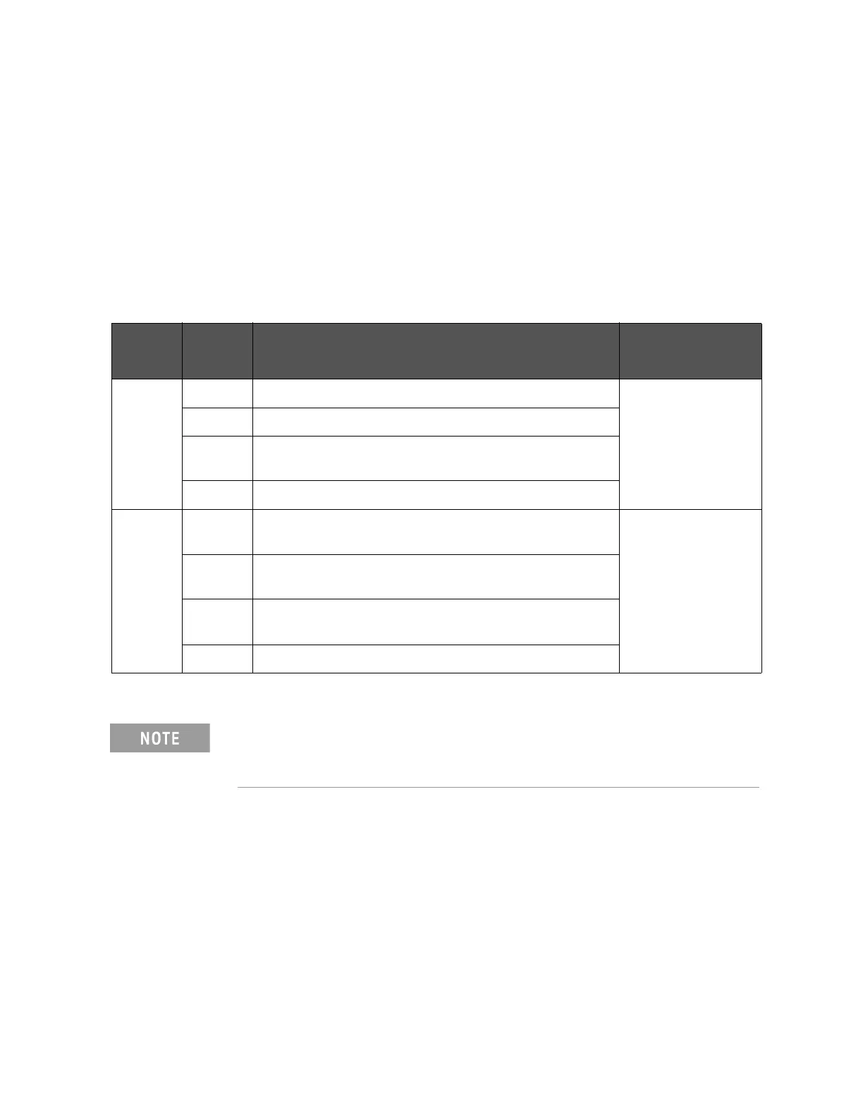
Table E-9 Internal jumper settings
Jumper
number
Jumper
position
1
Description Affected signals
JP1 1 Sets the pull-up voltage for output signals to +5 V (internal). /BIN1to /BIN9
/AUX_BIN
/OUT_OF_BIN
/PHI to /OVLD
2 Sets the pull-up voltage for output signals to +12 V (internal).
3(N) Sets the pull-up voltage for output signals to external voltage
(EXT.DCV1).
4 Not used.
JP2 1 Sets the pull-up voltage for output signals and the drive voltage for
input signals to +5 V (internal).
/INDEX
/EOM
/ALARM
/EXT_TRIG
/KEY_LOCK
/READY_FOR_TRIGGER
2 Sets the pull-up voltage for output signals and the drive voltage for
input signals to +12 V (internal).
3(N) Sets the pull-up voltage for output signals and the drive voltage for
input signals to +5 V through +15V (EXT.DCV2).
4 Not used.
1. The factory default setting is position (N) shown in the table above.
The handler interface board has labels “JP1” and “JP2” that indicate
where jumpers JP1 and JP2 are located.
Both jumpers JP1 and JP2 have a circle mark indicating their #1 side.