- 474 Keysight E4980A/AL User’s Guide
Handler Interface
Setting Up the Handler Interface Board
-
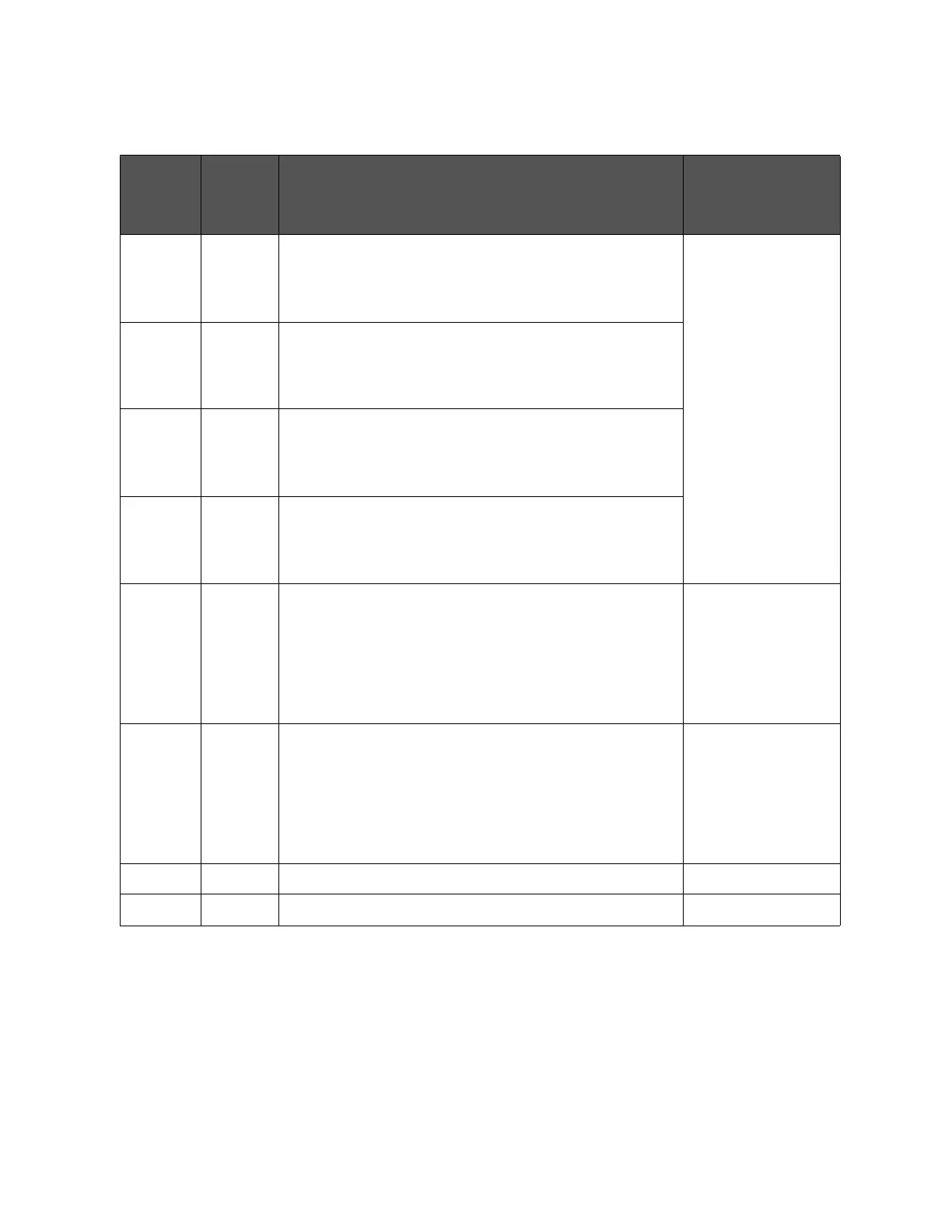
Table E-10 Bit switch (S1) settings
Bit
number
1
Factory
default
settings
Description Affected signals
1 Off When you set JP2 to 1 or JP2 to 3 and set EXT.DCV2 to 5 V through
6 V, set this bit to ON as well.
As a result, the input current limiting resistor for the /EXT_TRIG
signal is set to 316 .
/EXT_TRIG
2 Off When you set JP2 to 3 and set EXT.DCV2 to 6 V through 9 V, set
this bit to ON as well.
As a result, the input current limiting resistor for the /EXT_TRIG
signal is set to 562 .
3 On When you set JP2 to 2 or 3 and set EXT.DCV2 to 9 V through 15 V,
set this bit to ON as well.
As a result, the input current limiting resistor for the /EXT_TRIG
signal is set to 1 k.
4 Off When you set JP2 to 3 and set EXT.DCV2 to 15 V through 24 V, set
this bit to ON as well.
As a result, the input current limiting resistor for the /EXT_TRIG
signal is set to 2.27 k.
5 Off DC isolation switch for COM1.
When this switch is ON, COM1 is connected to the instrument's
circuit common line; therefore, the DC isolation output is not
isolated.
When this switch is OFF, the DC isolation output for COM1 is
isolated.
/BIN1to /BIN9
/AUX_BIN
/OUT_OF_BIN
/PHI to /OVLD
6 Off DC isolation switch for COM2.
When this switch is ON, COM2 is connected to the instrument's
circuit common line; therefore, the DC isolation output is not
isolated.
When this switch is OFF, the DC isolation output for COM2 is
isolated.
/INDEX
/EOM
/ALARM
/EXT_TRIG
/KEY_LOCK
/READY_FOR_TRIGGER
7-Not used. -
8-Not used. -
1. The bit numbers referenced in this table are the numbers printed on the bit switch (S1) of the handler interface board.