- 488 Keysight E4980A/AL User’s Guide
Scanner Interface
Signal Input/Output Connector
-
Scanner Interface I/O Connector Pin Assignments
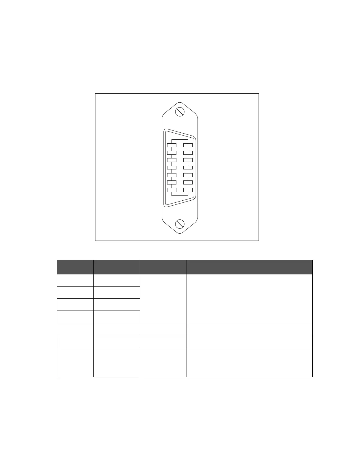
The pin assignments for the scanner interface I/O connector are shown in
Figure F-2 and Table F-7.
Figure F-2 Scanner interface I/O connector pin assignments
Table F-7 Scanner interface I/O connector pin assignments
Pin No. Signal Name Input/Output Description
1 /CH0 Input Channel Selection Signal
2/CH2
3/CH4
4/CH6
5 /CH_VALID Input Channel Valid Signal
6 /INDEX Output Analog Measurement Complete Signal.
7 EXT.DCV Input External DC Voltage.
Used as pull-up voltage of input/output signals.
The setting range is from 5 V to 15 V.
㪼㪋㪐㪏㪇㪸㫌㫁㪈㪈㪌㪊
㪈㪏
㪉㪐
㪊㪈㪇
㪈㪈㪋
㪈㪉㪌
㪈㪊㪍
㪈㪋㪎
㪆㪚㪟㪇 㪆㪚㪟㪈
㪆㪚㪟㪊
㪆㪚㪟㪌
㪆㪚㪟㪎
㪜㪯㪫㪶㪫㪩㪠㪞
㪆㪜㪦㪤
㪚㪦㪤㪤㪦㪥
㪆㪚㪟㪉
㪆㪚㪟㪋
㪆㪚㪟㪍
㪆㪚㪟㪶㪭㪘㪣㪠㪛
㪆㪠㪥㪛㪜㪯
㪜㪯㪫㪅㪛㪚㪭