- 498 Keysight E4980A/AL User’s Guide
Scanner Interface
Setting Up the Scanner Interface Board
-
Setting Up the Scanner Interface Board
When you use the scanner interface I/O signals, you must set the pull-up
resistor according to the external DC voltage (EXT. DCV) used with two
switches on the scanner interface board.
The bit switch setting procedure for the pull-up resistor setting is described
below.
Switch setting procedures
Step 1. Disconnect the power cable from the E4980A/AL and allow enough time (a
few minutes) for the internal capacitors to discharge.
Step 2. Remove the two screws that fix the scanner interface board to the
E4980A/AL’s rear panel.
Step 3. Pull off the scanner interface board and disconnect the connected flat cable.
Step 4. Remove the scanner interface board.
Step 5. Set two bit switches (S1, S2) referring to Table F-11 and Table F-12.
Disconnecting the scanner interface board from the unit while power is
supplied or immediately after turning off the power may damage the
scanner interface board and the E4980A/AL
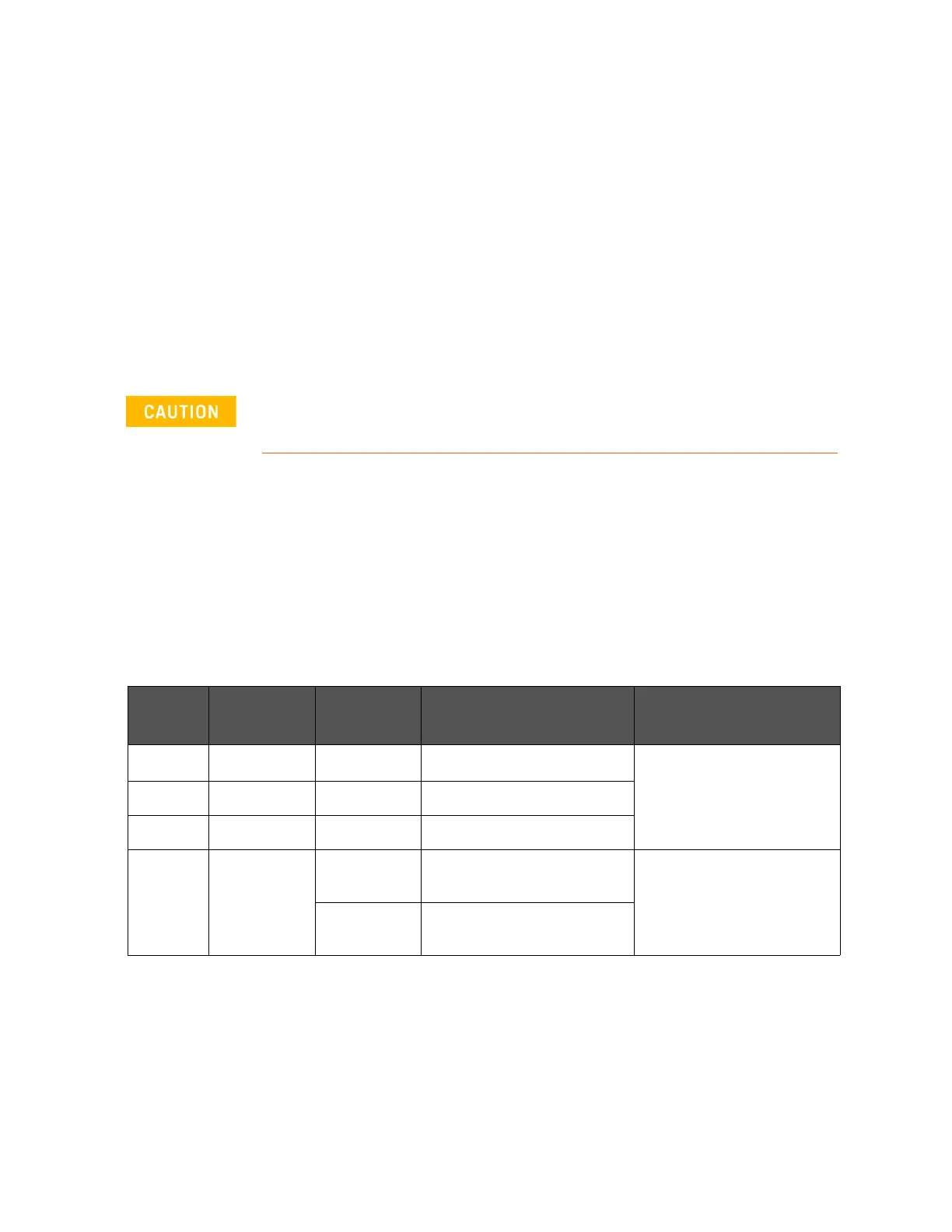
Table F-11 Setting Bit Switch (S1)
Bit Default Pull-up
Resistor
EXT. DCV Function
1
1
On 316 5 V EXT.DCV 6 V Switch for setting EXT_TRIG
input resistance
2
1
Off 562 6 V < EXT.DCV 9 V
3
1
Off 1 k 9 V < EXT.DCV 15 V
4 On 410
(when on)
5 V EXT.DCV 8 V Switch for setting /CH_VALID
input resistance
820
(when off)
8 V < EXT.DCV 15 V
1. For bits 1 to 3 of bit switch S1, only one bit can be turned on at one time.