Keysight E4980A/AL Precision LCR Meter 191
Measurement Procedure and Examples
Parallel/Series Circuit Mode
Selecting Circuit Mode of Capacitance
The following description gives some practical guidelines for selecting the
capacitance measurement circuit mode.
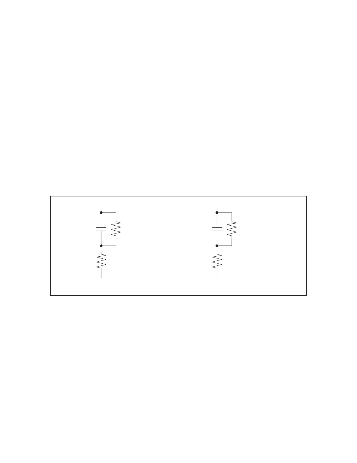
Figure 7-4 Capacitance circuit mode selection
The following rule of thumb can be used for selecting the circuit mode
according to the impedance of the capacitor.
For example, to measure a 20 F capacitor at 1 kHz (impedance will be
approx.8 ), the Cs-D or Cs-Q function is suitable.
Small Capacitance (modeled by (a) in Figure 7-4)
Small capacitance yields large reactance, which implies that the effect of the parallel
resistance (Rp) has relatively more significance than that of series resistance (Rs). The
low value of resistance represented by Rs has negligible significance compared with
the capacitive reactance, so the parallel circuit mode (Cp-D or Cp-G) should be used.
Large Capacitance (modeled by (b) in Figure 7-4)
When the converse is true and the measurement involves a large value of capacitance
(low impedance), Rs has relatively more significance than Rp, so the series circuit
mode (Cs-D or Cs-Q) should be used.
㪼㪋㪐㪏㪇㪸㫌㪼㪈㪇㪏㪇
Rs
Rp
Rs
Rp
㪤㫆㫉㪼㩷㫊㫀㪾㫅㫀㪽㫀㪺㪸㫅㫋
㪣㪼㫊㫊㩷㫊㫀㪾㫅㫀㪽㫀㪺㪸㫅㫋
㩿㪸㪀㩷㩷㩷㪪㫄㪸㫃㫃㩷㪚㩷㩿㩷㪿㫀㪾㪿㩷㪱㩷㪀
㪣㪼㫊㫊㩷㫊㫀㪾㫅㫀㪽㫀㪺㪸㫅㫋
㪤㫆㫉㪼㩷㫊㫀㪾㫅㫀㪽㫀㪺㪸㫅㫋
㩿㪹㪀㩷㩷㩷㪣㪸㫉㪾㪼㩷㪚㩷㩿㩷㫃㫆㫎㩷㪱㩷㪀
Above approx. 10 k Use parallel circuit mode
Below approx. 10 Use series circuit mode
Between above values Follow the manufacturer’s recommendation