38 Keysight N9927-90001 User’s Guide
Preparing for Initial Use of Your New FieldFox
Take the FieldFox Tour
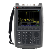
Top Panel
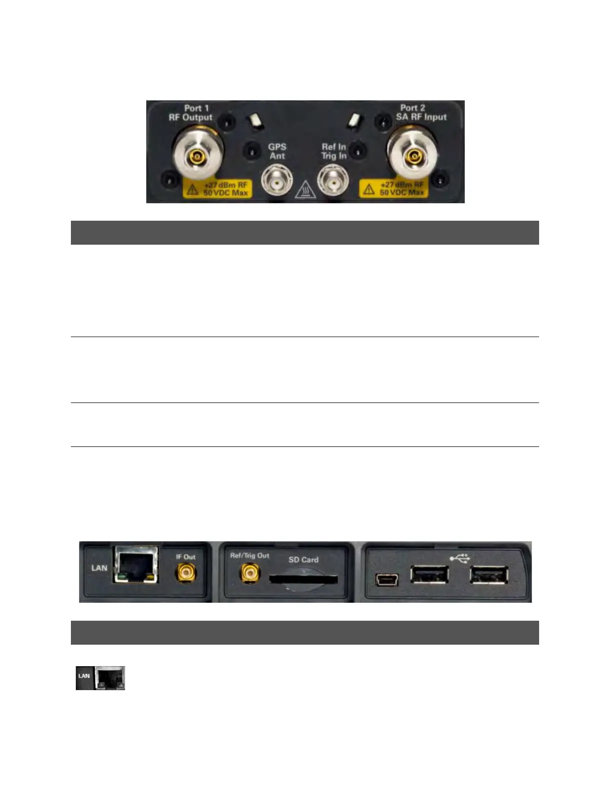
Right Side Panel
Caption Descriptions Learn More:
Port 1
RF Output
For CAT and NA measurements, use to make reflection measurements.
Maximum: ±50 VDC, +27 dBm RF
Also, for SA source output in SA mode.
“CAT Mode Settings”
on page 47
“NA Mode Settings” on
page 87
Chapter 9, “SA
(Spectrum Analyzer)
Mode”, on page 145
Port 2
SA RF Input
For SA, use to make all measurements.
For CAT, NA, and VVM mode, use to make Port 2 transmission
measurements.
Maximum: ±50 VDC, +27 dBm RF.
“SA Mode Settings” on
page 148
GPS Ant SMA (f) connector for use with built-in GPS. Produces a 3.3 VDC bias
voltage for the antenna pre-amplifier. Use with a GPS antenna such as
N9910X-825. Other GPS antennas can also be used.
“GNSS (GPS+) and
GPS” on page 526
Ref In
Trig In
SMA (f) connector for use with Frequency Reference Source and External
Trigger Input signal.
Maximum: 5.5 VDC.
“Frequency Reference
Source” on page 530.
“Triggering” on
page 172
Connector Description Learn More:
Ethernet cable connector to read trace data using the FieldFox Data Link
Software and connect to the FieldFox remotely.
Download the latest version of the software at:
www.keysight.com/find/fieldfoxsupport
“LAN Settings” on
page 535