26 Keysight CX3300 User’s Guide, Edition 4
Setting Up the CX3300
Verifying Basic Operation
Procedure
1. Set the slide switch on the test adapter to the 50 OHM. See Figure 1-6.
2. Connect the coaxial cable between the BNC jack connector on the test
adapter and the Aux Out terminal on the CX3300 front panel.
3. Connect the CX1105A to the connection posts on the test adapter as shown
in Figure 1-6.
4. Press the
1 (yellow), 2 (green), 3 (blue), or 4 (red) key associated with the
channel connected to the Aux Out terminal and enable the channel.
5. Press the
Menu key several times to open the Configuration dialog box. The
Menu key is located above the Horizontal control on the front panel.
6. Set the following conditions on the dialog box (Configuration > Calibration
Output).
• Output State: ON
• Source Shape: Square
The +5 V square pulse (1 kHz, 50% duty
cycle) is applied from the Aux Out
terminal which has 50 output impedance.
7. Click the close (x) button located in the upper right corner on the
Configuration dialog box to close the dialog box.
8. Press the
Run key to start waveform acquisition.
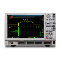
9. Use the Vertical control knob to adjust the vertical scale. You will see square
pulse (approximately +2.5 V, divided by two 50 ) as shown in Figure 1-6.
Figure 1-6 Test Adapter and Calibration Output
Slide switch50 OHM
BNC jack connector
-
+
GND
Connection posts
for connecting
the CX1105A