Keysight CX3300 User’s Guide, Edition 4 39
Using the CX3300
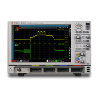
Front Panel Overview
Front Panel Overview
This section describes the front panel of the CX3300.
Figure 2-1 Front Panel
1. Standby switch
Turns the instrument on. Pressing the button in the ON state makes it in the
standby state. The green LED lights when it is in the ON state.
2. Aux Out terminal
BNC connector used to apply one of the following reference signals. The
output signal can be set by using the Co
nfiguration dialog box. For the square
pulse, the base voltage is 0 V and the output impedance is 50 .
• DC current: -200 mA to +200 mA
• DC voltage: -7 V to + 7 V
• Square: +5 V square pulse, 1 kHz, 50% duty cycle
• Pulse: +5 V square pulse, 20 ns to 1 ms period, programmable duty cycle