Setting Up the Oscilloscope 1
Keysight Infiniium S-Series Oscilloscopes User’s Guide 17
Connecting Oscilloscope Probes
1 Attach the probe connector to the desired oscilloscope channel or trigger input
using the probe instructions.
2 Connect the probe to the circuit of interest using the browser or other probing
accessories.
3 Disconnect the probe.
.
The Keysight Infiniium S-Series oscilloscopes are not rated for Measurement
Category II, III, or IV.
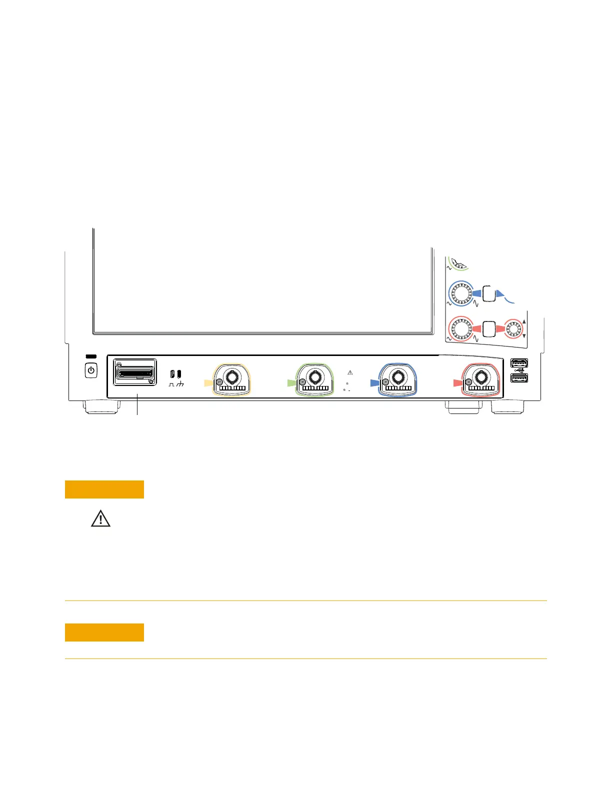
Figure 3 S-Series oscilloscope probe connectors
Do not exceed the maximum input voltage rating.
The maximum input voltage for the 50 Ω input impedance setting is ±5 V.
The maximum input voltage for the 1 MΩ input impedance setting is 30 Vrms or
±40 Vmax (DC+Vpeak)
Probing technology allows for testing of higher voltages; the included N2873A 10:1
probe supports 300 Vrms or ±400 Vmax (DC+Vpeak). No transient overvoltage
allowed.
Push
for Vernier
Push
to Zero
DIGITAL D15-D0
1
2
3
4
All Inputs
1M Ω ±40V MAX
50
5V MAX
1M
~
~
14pF
Probe Comp
+
3
4
Digital channels input
4 analog input channels where
probes are connected
When measuring voltages over 30 V, use a 10:1 probe.