196 Keysight NFA Series Noise Figure Analyzers Service Guide
RF Section Troubleshooting (N8973B, 74B, 75B Analyzers)
Troubleshooting
A12 YTF Preselector Power Level Verification
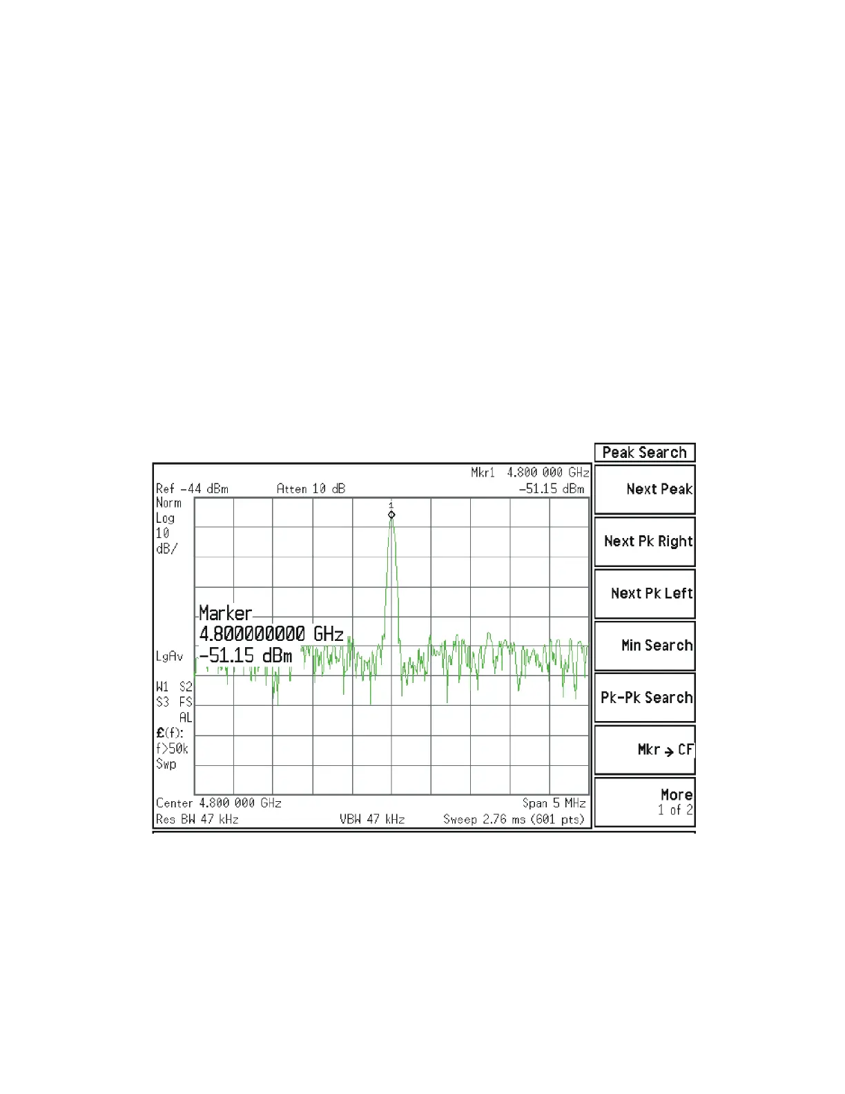
Press Input/Output, RF Calibrator, 4.8 GHz, AMPTD, Attenuation, Mech
Atten, 10 dB, Zero Span on the analyzer. Measure the 4.8 GHz calibrator on
the output of W7 cable using a functioning spectrum analyzer. When the
4.8 GHz calibrator signal is used, there will be ~ 5 dB ± 4 dB of insertion loss
through the YTF Preselector. The tolerance is large because the A12 YTF loss
varies between devices, and the YTF might not be perfectly aligned, or the
frequency response adjustment may be required.
To perform the YTF alignment, reconnect W7 and press System, Alignments,
Ad vanced, Characterize Preselector. The routine may take several minutes to
align the YTF. Display the 4.8 GHz calibrator on screen as explained in the
quick check section. If the signal level is still incorrect, suspect all assemblies,
cables, and switches between the W7 cable and the output of the A11 Low
Band Switch.
Reconnect W7 and W8 cables.
Figure 4-36 4.8 GHz Calibrator Signal at Output of W7 Cable
If the power level is incorrect, the most probable cause is the YTF Preselector.
Reconnect W7 and W8 cables.
The following High Band path items have been verified in the RF section:
— 4.8 GHz Calibrator signal power level from the A16 Reference Board
— 1st L.O. power level from the A14 L.O. Synthesizer
— Switch control logic from the A15 Front End Control Board to: