450 Keysight NFA Series Noise Figure Analyzers Service Guide
Assembly Replacement Procedures
Motherboard Assembly
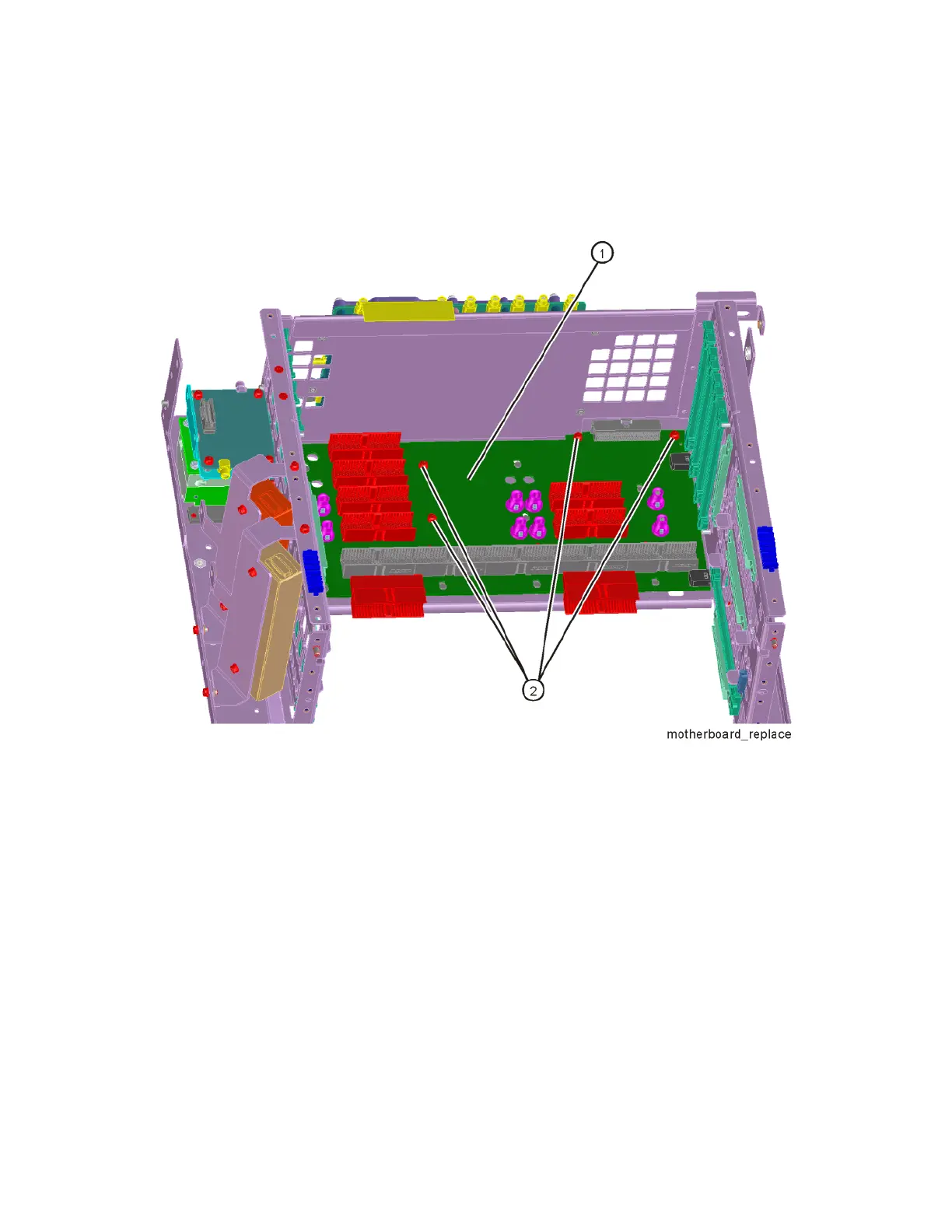
16.Refer to Figure 15-47. Remove the motherboard (1) by removing the four
screws (2).
Figure 15-47 Motherboard Assembly Removal
Replacement
1. Refer to Figure 15-47. Place the motherboard (1) into position in the
chassis and replace the four screws (2 ). Torque to 9 inch-pounds.
2. Refer to Figure 15-46. Replace the left side chassis by replacing the seven
screws. Torque to 9 inch-pounds.
3. Refer to Figure 15-44. Replace the midplane bracket (1) by replacing the
eight screws (2) . Torque to 9 inch-pounds.
4. Replace the fan assembly. Refer to the Fan Assemblyreplacement
procedure.
5. Replace the RF bracket. Refer to Figure 15-8 on page 400. Torque the
screws to 9 inch-pounds.