Keysight NFA Series Noise Figure Analyzers Service Guide 437
Assembly Replacement Procedures
A5 Solid State Drive
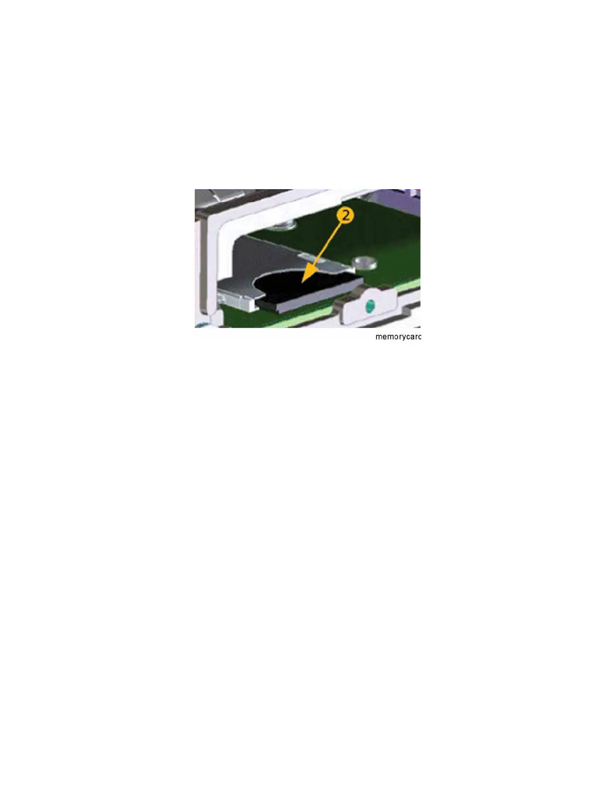
A4A1 CPU Memory Card
1. Refer to Figure 15-37. Remove the SSD as described on page 435. The
memory card (2) can be removed by pushing on the memory card and it
will spring out. To install the memory card push it into the slot until you
feel the spring catch. Then replace the SSD as described on page 436.
Figure 15-37 CPU Memory Card Removal
Disk Drive Interconnect
Removal
1. Remove the A5 Disk Drive assembly for the instrument. Refer to the “A5
Solid State Drive” removal procedure.
2. Remove the A4 CPU assembly from the instrument. Refer to the “CPU
Assembly” removal procedure.
3. Refer to Figure 15-38. Remove the A4 CPU assembly cover (1 ) by first
removing the 19 flat-head screws (2) and 3 pan-head screws (3). The 19
flat-head screws need to be discarded and replaced since they are
precoated with a thread locking compound and new screws will need to be
used when the cover is re-installed.