210 Keysight NFA Series Noise Figure Analyzers Service Guide
RF Section Troubleshooting (N8976B)
Troubleshooting
A9 Input Attenuator and A10 Input Attenuator Verification
Calibrator Switch Test
On the A16 Reference assembly, disconnect semi rigid cable W3 from A16J701
and measure A16J701 with a spectrum analyzer. Expected signal is 50 MHz at
−25 dBm ± 0.5 dB (RF calibrator set to 50 MHz). If signal level is incorrect,
suspect A16 Reference assembly is faulty, or the 50 MHz calibrator amplitude
requires adjustment using the field calibration software.
To verify calibrator switch operation, connect external signal source set to
50 MHz and −25 dBm to the RF input connector of analyzer under test. Press
Input/Output, RF Calibrator, Off. If the signal level at the attenuator output is
now correct, suspect the A9 Attenuator cal switch or a faulty control signal
from the A15 Front End Controller assembly.
Attenuator Check
Set the signal source connected to the analyzer input port to 0 dBm. On the
analyzer, press Amplitude, Attenuation, and change input attenuation to 0 dB.
The measuring spectrum analyzer connected to A10 Attenuator output port
should indicate a 0 dBm level.
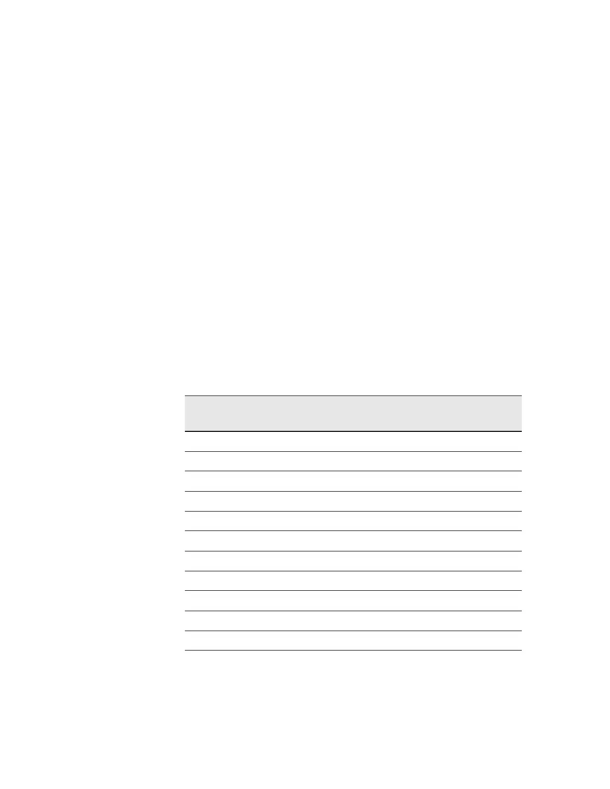
Change the input attenuation on the analyzer under test to 2 dB. See the chart
below for expected measurement values at the A10 Attenuator output port.
Analyzer Under Test
Attenuator Setting (dB)
Power at A10
Output Port (dBm)
Input Attenuator Being Tested
(N8976B)
0 0 dBm (reference) Both set to through path
2 −2A9
4 −4A9
6 −6 A9
8 −8A9
10 −10 A10
20 −20 A10
30 −30 A10
40 −40 A10
50 −50 A10
60 −60 A10