Functions and Measurements
Making Distortion Measurements
50
Making Distortion Measurements
This section provides information on measuring and
identifying signal distortion.
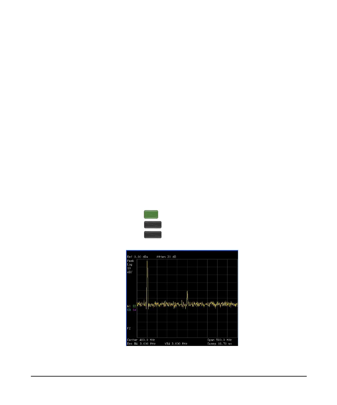
Identifying Analyzer Generated Distortion
High- level input signals may cause analyzer distortion
products that could mask the real distortion measured on
the input signal. Use trace and the RF input attenuator to
determine which signals, if any, are internally generated
distortion products.
In this example, we use the RF output of a signal generator
to determine whether the harmonic distortion products are
internally generated by the analyzer.
1 Connect the signal generator to the analyzer RF IN.
2 Set the source frequency to 200 MHz, amplitude to 0 dBm.
3 Set the analyzer center frequency and span:
Press > Preset
Press > 400 > MHz
Press > 500 > MHz
Figure 3-16 Harmonic Distortion
Preset/
System
Frequency
SPAN