7-17
September 2004
Argonite
®
Engineered Fire Suppression System
38-KFSARG-000
All parts of the supporting equipment must be fabricated and installed so that they
will not be disengaged or distorted by movement of the supported pipe. A pipe line
is not to be supported from another pipe line.
All pipe supports shall be installed to avoid interference with other piping, hangers,
electrical conduit, and supports or building structure and equipment.
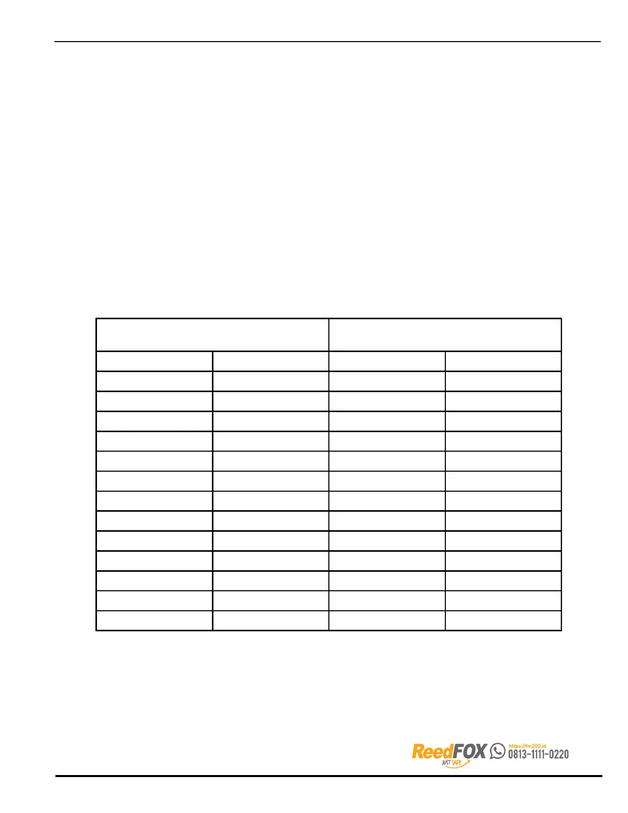
Supports shall be sufficiently close together to avoid excessive bending stresses
from concentrated loads between supports. Spacing between supports is shown in
Table 7-10.
Where rod type hangers are permitted for intermediate support between rigid supports,
they shall be a steel clevis hanger of the proper size for the supported pipe and
with solid bar-type hanger rod. See Table 7-11 on the following page for rod sizes.
Hanger rods shall not be subjected to stresses due to bending.
Note: C clamps are not acceptable to support rod hangers.
Generally it is acceptable to alternate hangers on rods. Where an intermediate hanger is
used between two rigid supports, the distance between hangers shall be reduced to
approximately 75 percent of the distances shown in Table 7-10.
Table 7-10. Maximum Spacing Between Pipe Supports for Screwed, Welded or Grooved Pipe
Nominal Pipe Size Maximum Span
in. mm ft. m
1/4 8 5 1.5
1/2 15 5 1.5
3/4 20 6 1.8
12572.1
1¼ 32 8 2.4
1½ 40 9 2.7
250103.0
2½ 65 11 3.4
380123.7
4 100 14 4.3
5 125 16 4.9
6 150 17 5.2
8 200 19 5.8