8-3
September 2004
Argonite
®
Engineered Fire Suppression System
38-KFSARG-000
8-3 ARGONITE CYLINDER ASSEMBLY
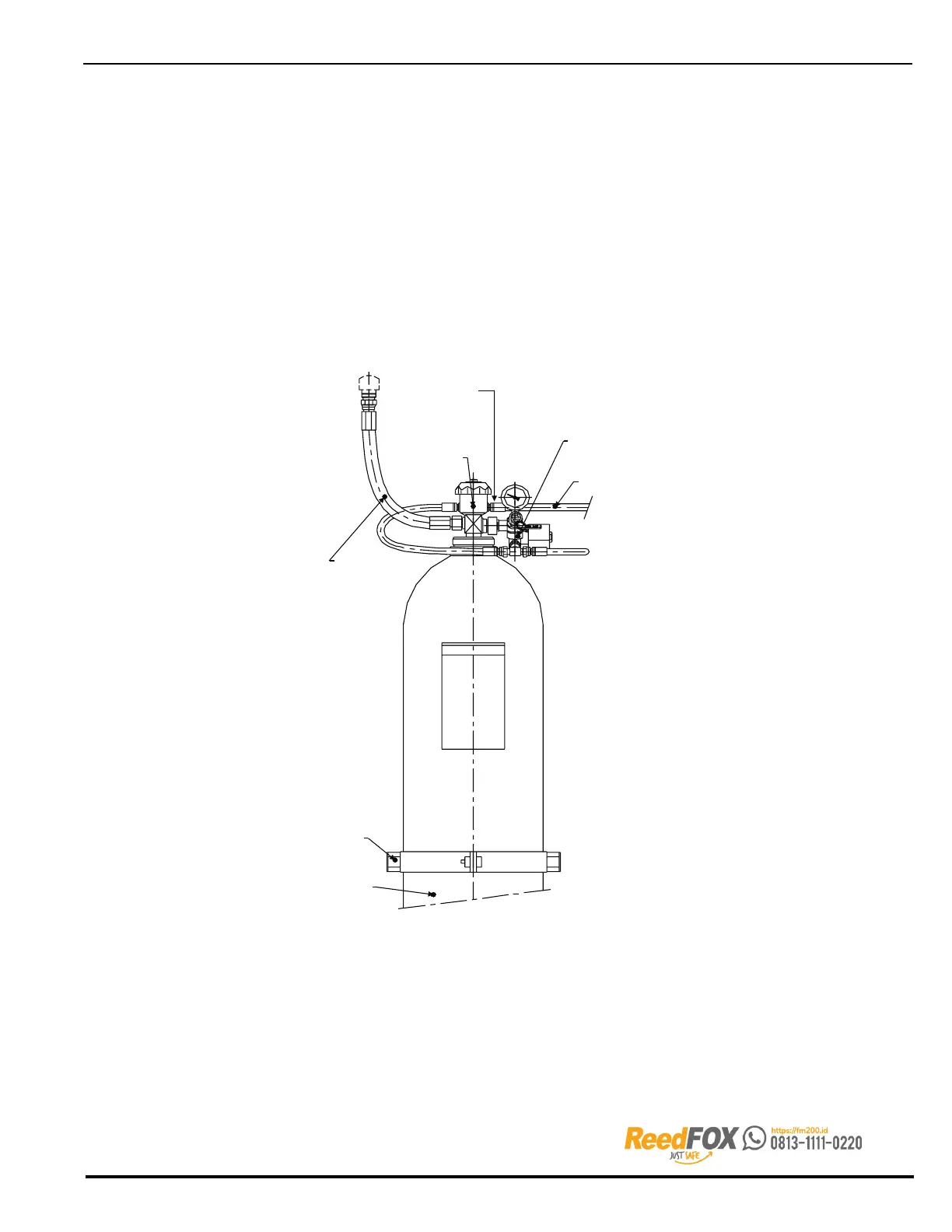
Visually check the following:
The Argonite Cylinder is installed and secured in its mounting bracket.
The discharge hose is connected to the check valve on the manifold and to the discharge
port on the cylinder valve.
The pneumatic actuator is fitted on the connection port on the Argonite cylinder valve.
The pressure gauge or pressure gauge solenoid valve unit is fitted on the port of the
Argonite cylinder valve.
The actuator hose from the pressure gauge solenoid valve unit is fitted on the free port
of the tee piece.
Refer to the following figures for system details. Figures 6-15 and 6-16 can also be referenced.
ARGONITE
CYLINDER
BRACKET
DISCHARGE
HOSE
CYLINDER
VALVE
PNEUMATIC
ACTUATOR
PRESSURE GAUGE
OR PRESSURE
GAUGE/SOLENOID
VALVE ASSEMBLY
PILOT HOSE (TO
SLAVE CYLINDERS)
Figure 8-1. Argonite Cylinder Valve Assembly