TOS5051A/5050A 2-5
Chap.2
Installation and Preparation
Testers that operate on other AC line voltages as shown below also are available as
factory-modification options.
The following table is printed on the rear panel of the tester. If nothing is marked in
the “SETTING SUPPLY” column, the nominal voltage is 100 V. The change in the
nominal voltage is made at the factory. If a change has been made, a mark is indi-
cated to the left of the corresponding voltage.
Before turning ON the AC input power of the tester, be sure that your AC line volt-
age conforms with the nominal voltage indicated on the indicator sheet.
• Do not modify your tester by yourself. Consult Kikusui distributor/agent to
have your tester modified.
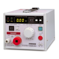
2.5 Connecting the Power Cord
• This product is designed to be connected to a power supply classified as
overvoltage category II. Do not connect to a power supply classified as
overvoltage category III or IV.
• Do not use the power cord that comes with the product as a power cord
for other equipment.
1. Check that the AC power supply is within the input power supply range
of the product.
2.
Check that the POWER switch is turned OFF.
3.
Connect the power cord to the AC LINE connector on the rear panel.
4.
Insert the power plug to the outlet.
• The tester should be connected to a stable AC power supply.
From the tester’s internal circuit configuration of view in the AC withstanding
voltage test, the output voltage is affected by fluctuations of the AC power supply.
Optional AC line voltages 110 V 120 V 220 V 230 V 240 V
SETTING SUPPLY LINE VOLTAGE
STANDARD 100 V
110 V
120 V
220 V
230 V
240 V
WARNING
WARNING
NOTE