7-2 TOS5051A/5050A
7.1 Connecting the Cable
1. Turn OFF the POWER switch on the tester and the device to be con-
nected.
2.
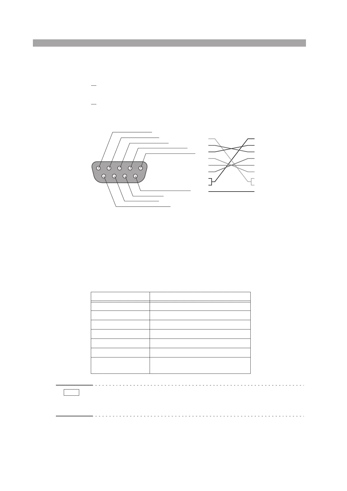
Connect a cross RS-232C cable to the 9-pin RS-232C connector on the
rear panel of the tester.
Fig. 7-1 shows the connector pin assignments.
Fig. 7-1 9-pin AT type connector
7.2 RS-232C Specifications
The protocol is fixed and you cannot change it.
Table 7-1 RS-232C Specifications
• When the tester is turned on, a few bytes of characters may be transmitted from
the tester. Turn on the power to the PC or serial printer after turning on the power
to the tester.
Item Specifications
Transmission system Start-stop synchronization, half-duplex
Transmission rate 9600 bps
Data Length 8 bits
Parity None
Stop bit 1 bit
Handshaking None
Delimiter
When sending: CR+LF
When receiving: CR, LF, or CR+LF
1: CD (carrier detect)
2: RXD (receive data)
3: TXD (transmit data)
4: DTR (data terminal ready)
5: GND (signal ground)
6: DSR (data set ready)
7: RTS (ready to send)
8: CTS (clear to send)
9: RI (ring indicator) on the tester
Tester end
1
2
3
4
5
6
7
8
9
1
2
3
4
5
6
7
8
9
D-sub 9 pin
female
D-sub 9 pin
female
Cross cable example
NOTE