TOS5051A/5050A 4-19
Chap.4
Description of Front and Rear Panel Items
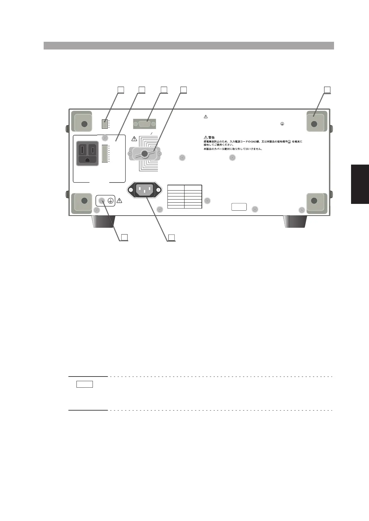
4.3 Description of Rear Panel Items
[35] Protective conductor terminal
This terminal is for grounding the tester to an earth ground.
For your safety, be sure to ground the tester. For a description of the grounding
method, see section 2.6, “Grounding (Earth)” (Page 2-6).
[36] AC LINE connector
The AC LINE connector is for the AC input power.
[37] SIGNAL I/O connector
The SIGNAL I/O connector is a 14-pin Amphenol connector for the interlock input
signal*, remote control signal for test start/stop, and status output signal. For
details, refer to section 6.3.3, “Interlock Function” (Page 6-24) or section 6.3.2,
“Remote Control through the SIGNAL I/O Connector” (Page 6-21).
• * The Interlock signal input pin assignments are different from the old model
TOS5050/5051. Therefore, the 14-pin Amphenol plug that is supplied with the tester
cannot be shared between the new and old models.
H.V ON
TEST
PASS
U FAIL
L FAIL
READY
PROTECTION
POWER ON
OFF ON
OFF ON
TEST MODE
RS232C
SIGNAL I O
7
:
READY
6
:
L
FAI L
5
:
U
FAIL
4
:
PASS
3
:
TEST
2
:
H.V ON
1
:
INTERLOCK
+
8
:
PROTECTION
9
:
INTERLOCK
-
10
:
RR START
11
:
RR STOP
12
:
RR ENABLE
13
:
ISOL COM
14
:
ISOL COM
DOUBLE ACTION
PASS HOLD
MOMENTARY
FAIL MODE
USE ONLY
BUZZER AND
WARN ING L I GH T
AC10 0V 0
.3A MA X
STATUS OUT
WARNING
TO AVOID ELECTRIC SHOCK, THE POWER CORD PROTECTIVE GROUNDING
CONDUCTOR OR THE PROTECTIVE CONDUCTOR TERMINAL MUST BE
CONNECTED TO GROUND.
DO NOT REMOVE COVERS, REFER SERVICING TO QUALIFIED PERSONNEL.
KIKUSUI ELECTRONICS CORP.
MADE IN JAPAN
100V
LINE VOLTAGE
STANDARD
SETTING
SUPPLY
110 V
120V
220V
230V
240V
AC LINE 50 60Hz
800VA MAX
No.
IF THIS COLU MN IS BLANK,
THE UNIT IS WIRED IN 100V
35
36
37
38
40
39
41
NOTE