TOS5051A/5050A 10-5
Chap.10 Specifications
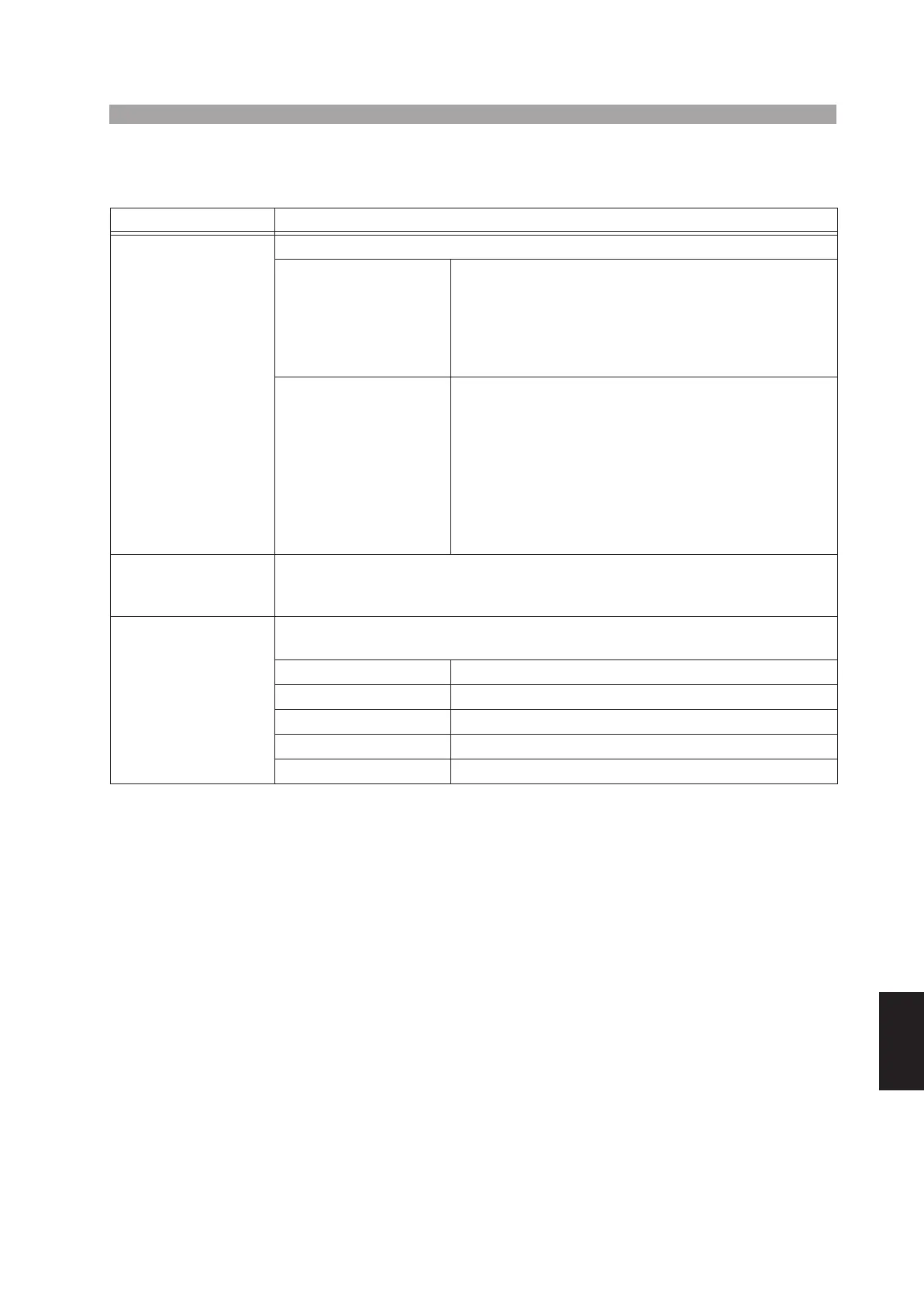
10.2 Interface and Other Functions
7
SIGNAL I/O input
The signal input is isolated from the internal circuit (30 VDC/30 VACrms
MAX). However, the common is shared with the signal output circuit.
The input pins are pulled up to +15 V by a resistor. Opening an input pin is
equivalent to entering a high level signal.
Item TOS5050A/TOS5051A
Remote control function
The tester has the following functions for remote-control of test start/stop.
REMOTE connector
(5-pin DIN connector on
the front panel)
• To control the tester from an optional
Remote control box RC01-TOS or RC02-TOS.
• To control the tester from an optional
High voltage test probe HP01A-TOS or HP02A-TOS
(when the test voltage is less than 4 kVACrms or 5 kV
DC).
SIGNAL I/O connector
(14-pin Amphenol con-
nector on the rear
panel)
• To control the tester from a make-contact device
(such as a relay or a switch).
• To control the tester with a low-active control
signal from a logic circuit.
Conditions of low-active control signal
7
• High level input voltage: 11 V to 15 V
• Low level input voltage: 0 V to 4 V
• Low level input current: -5 mA Max.
• Input time requirement: 5 ms Min.
Interlock The tester accepts an interlock input signal applied through function the SIGNAL I/O
connector (14-pin Amphenol connector on the rear panel). When this signal is applied,
the tester drives itself into the PROTECTION status.
RS-232C D-SUB 9-pin connector on the rear panel (conforms to EIA-232-D)
Outputs test data and test results
Transmission system Start-stop synchronization, half-duplex
Transmission rate 9600 bps
Data Length 8 bits
Parity None
Stop bit 1 bit
 Loading...


