TOS5051A/5050A 4-13
Chap.4
Description of Front and Rear Panel Items
4.2 Display Items
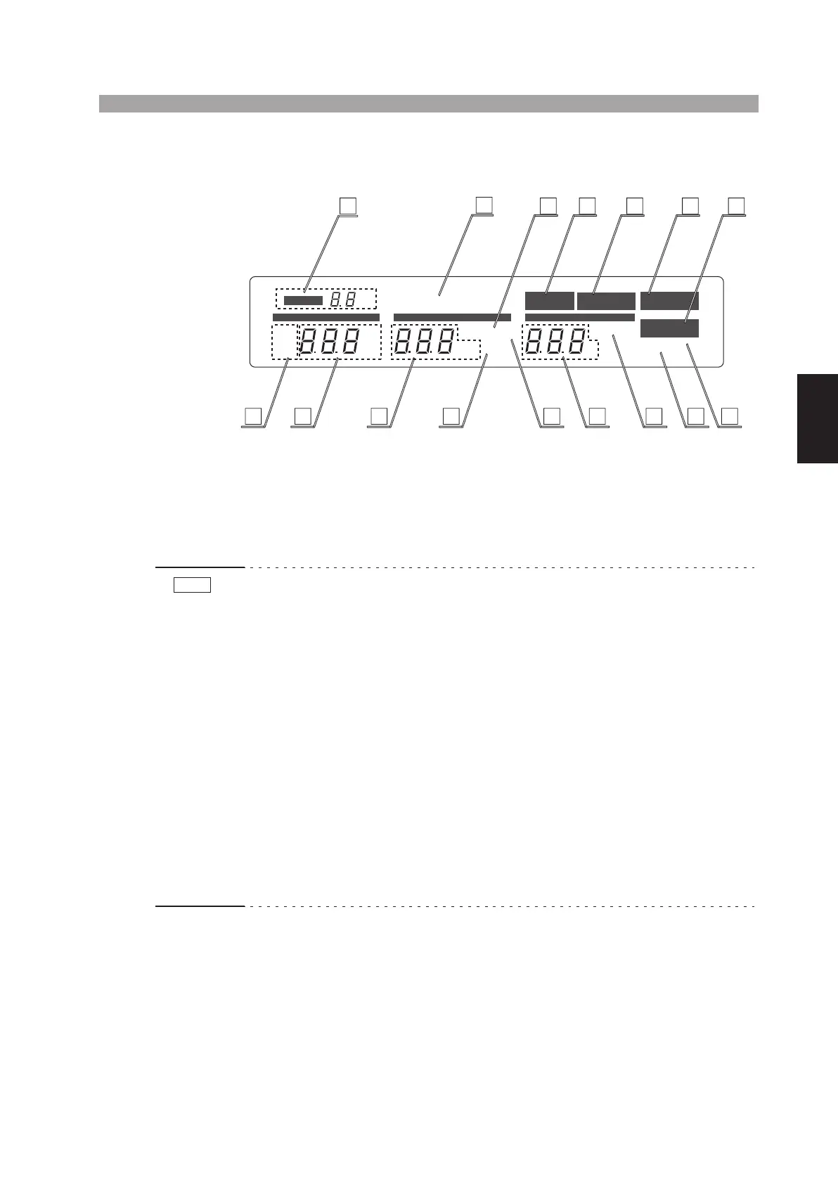
Fig. 4-3 Fluorescent display
[19] TEST VOLTAGE RANGE message
This message, which is a 7-segment 2-digit message, indicates the test voltage range
selected with the TEST VOLTAGE switch. The selectable test voltage ranges are 5
kV or 2.5 kV.
• When you change test voltage ranges with the TEST VOLTAGE switch, the TEST
VOLTAGE RANGE message blinks to indicate that the ranges have been
changed. Blinking stops when you press the STOP switch or when you start the
test by pressing the START switch.
• During the TEST-ON period (period that the “TEST” message appears), the TEST
VOLTAGE switch is disabled. During this period, it is possible that the actual
position of the switch does not conform with the TEST VOLTAGE RANGE mes-
sage or the AC/DC test mode message.
• Do not let the TEST VOLTAGE switch get caught between two range positions. If
you turn ON the POWER switch while the TEST VOLTAGE switch is caught in
the middle, the test voltage range message shows a blinking “0 kV” to notify that
the setting has not been confirmed (in addition, if the TOS5051A is in the middle
of switching between AC and DC, both “AC” and “DC” light up simultaneously).
If this happens, turn the TEST VOLTAGE switch accurately to a range position.
When you do so, the tester will enter the READY status (“READY” is lit). In this
status, blinking stops when you press the STOP switch or when you start the test
by pressing the START switch.
PROTECTION
READY
TEST PASS
AC
kV
mA
FAIL
DC
s
CURRENT TIME
UPPER LOWER
KEYLOCK
REMOTE
TIMER ON
LOWER ON
UPPER
LOWER
RANGE
kV
VOLTAGE
20
28
19
32
25 29 30 31
21 22 24 3334272623
NOTE