5-2 TOS5051A/5050A
■ Be sure to read Chapter 3 “Handling Precautions” and
observe the instructions given there.
5.1 Initial Setup
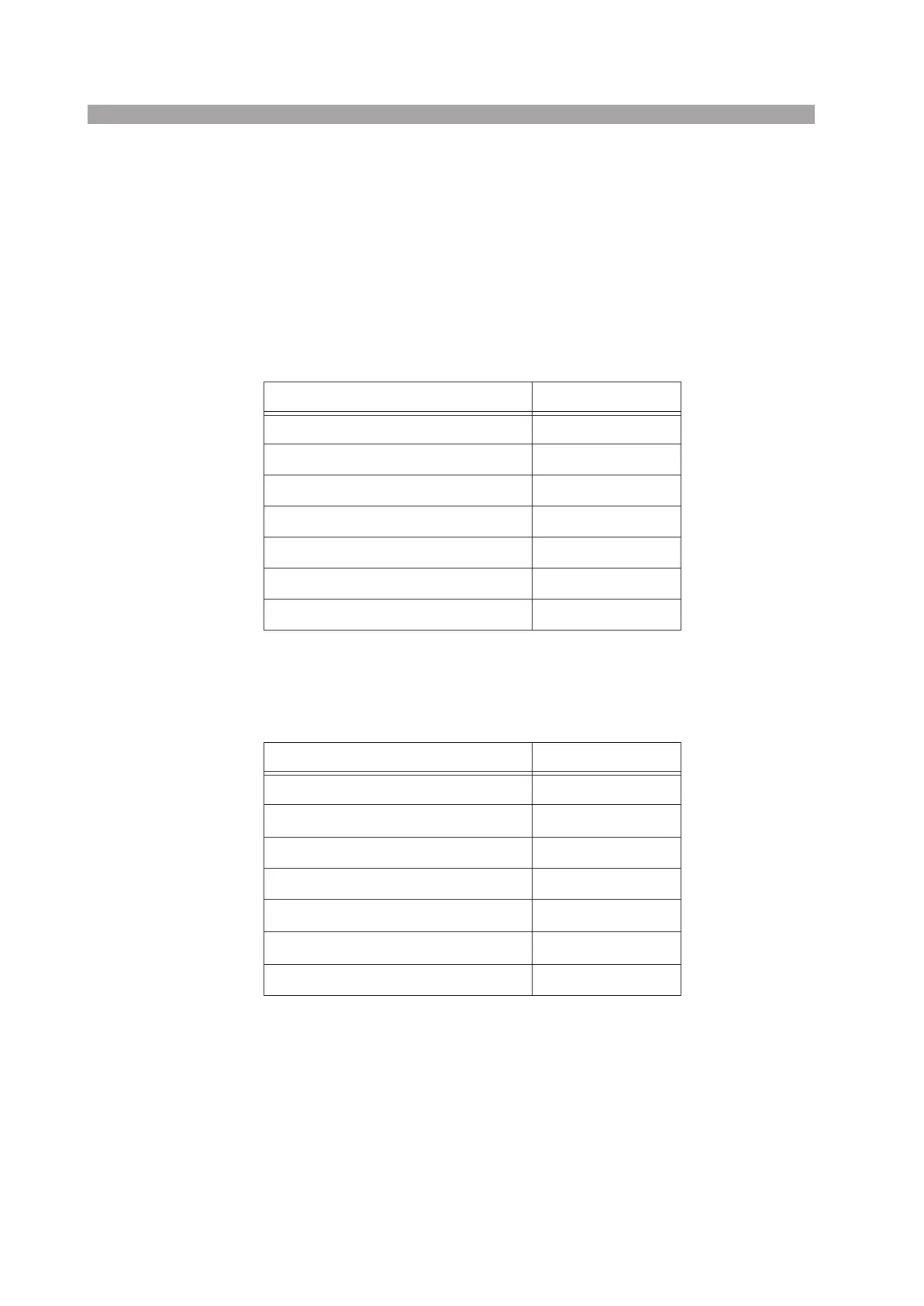
Table 5-1 shows the initial setup (factory default setup) of the switches and knobs
on the panels.
Table5-1 Factory default setup of switches and knobs
Table 5-2 shows the initial setup (factory default setup) of the setup data stored in
the internal memory of the tester.
Table 5-2 Factory default setup data
Item Setting
POWER switch OFF position
TEST VOLTAGE switch 2.5 kVAC range
TEST VOLTAGE control “0” position
Zero adjustment of analog voltmeter “0” position
BUZZER volume adjustment Fully clockwise
TEST MODE switches OFF for all
STATUS SIGNAL switches OFF for all
Item Initial setup data
Upper cutoff current 0.2 mA
Lower cutoff current
0.1 mA
Lower pass/fail judgment OFF
Test period 0.5 s
Timer function
ON
Keylock function
0FF
Talk mode 0