TOS5051A/5050A 5-5
Chap.5
Preparative Test Procedures
7. Check that the PROTECTION status (“PROTECTION” is lit) is enabled
by the interlock function.
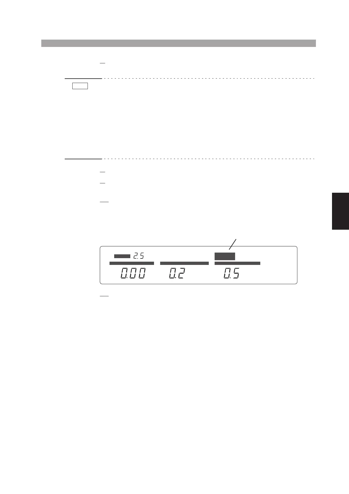
• Do not let the TEST VOLTAGE switch get caught between two range positions. If
you turn ON the POWER switch while the TEST VOLTAGE switch is caught in
the middle, the test voltage range message shows a blinking “0 kV” to notify that
the setting has not been confirmed (in addition, if the TOS5051A is in the middle
of switching between AC and DC, both “AC” and “DC” light up simultaneously).
If this happens, turn the TEST VOLTAGE switch accurately to a range position.
As you do so, the tester will enter the READY status (status that the “READY”
message appears). In this status, blinking stops as you press the STOP switch.
• The digital voltmeter may not display 0.00 kV.
8.
Turn OFF the POWER switch.
9.
Connect the 14-pin Amphenol connector (supplied as an accessory) to
the SIGNAL I/O connector.
10.
Wait at least one minute. Turn the POWER switch back ON.
After several tens of seconds, the fluorescent display shows the version num-
ber, model name, and talk mode number.
After a few more seconds, the initial test setup data will appear again.
11.
Check that the tester is in the READY status (“READY” is lit).
NOTE
PROTECTION
READY
TEST PASS
AC
kV
mA
FAIL
DC
s
CURRENT TIME
UPPER LOWER
KEYLOCK
REMOTE
TIMER ON
LOWER ON
UPPER
LOWER
RANGE
kV
VOLTAGE
L
g
ts
up