TOS5051A/5050A Safety Precautions VII
Fr
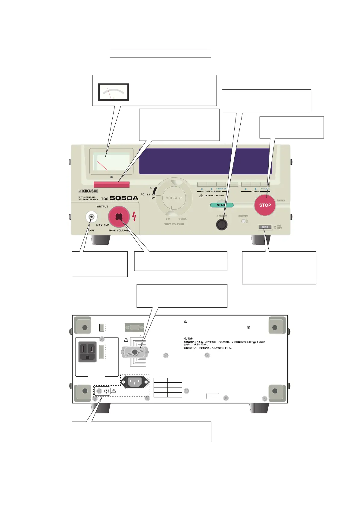
ont Panel and Rear Panel
• When accessing the panels, be sure to read chapter 3, “Handling Precautions.”
H.V ON
TEST
PASS
U FAIL
L FAIL
READY
PROTECTION
POWER ON
OFF ON
OFF ON
TEST MODE
RS232C
SIGNAL I O
7
:
READY
6
:
L
FAI L
5
:
U
FAIL
4
:
PAS S
3
:
TEST
2
:
H.V ON
1
:
IN TERLOCK
+
8
:
PROTECTION
9
:
IN TERLOCK
-
10
:
RR START
11
:
RR STOP
12
:
RR ENABLE
13
:
ISOL COM
14
:
ISOL COM
DOUBLE ACTION
PASS HOLD
MOMENTARY
FAIL MOD E
USE ONLY
BUZZER AND
WARNI NG LI GH T
AC10 0V 0
.3A MA X
WARNING
TO AVOID ELECTRIC SHOCK, THE POWER CORD PROTECTIVE GROUNDING
CONDUCTOR OR THE PROTECTIVE CONDUCTOR TERMINAL MUST BE
CONNECTED TO GROUND.
DO NOT REMOVE COVERS, REFER SERVICING TO QUALIFIED PERSONNEL.
KIKUSUI ELECTRONICS CORP.
MADE IN JAPAN
10 0 V
LINE VOLTAGE
STANDARD
SETTING
SUPPLY
110 V
120V
220V
230V
240V
AC LINE 50 60Hz
800VA MAX
No
.
IF THIS CO LUM N IS BLAN K,
THE UNIT IS WIRED IN 100V
STATUS OUT
Be sure to stop the tester
before changing test
parameters.
Be sure to read the manual before
controlling the tester remotely.
See section 2.6, “Remote Control.”
DANGER!
HIGH VOLTAGE Output Terminal
Start connecting from
the low voltage test
lead.
Deflected meter pointer means
hat the tester is in the
“DANGER! HIGH VOLTAGE”
state.
Lighted lamp means that the
tester is in the
“DANGER! HIGH VOLTAGE”
state.
For your safety, be sure to connect to the earth ground.
See section 2.6, “Grounding (Earth).”
Before turning ON the
POWER switch, be certain
that the TEST VOLTAGE
control is in the “0” position.
Be sure to read the manual before
controlling the tester remotely.*
See section 2.6, “Remote Control.”
* The SIGNAL I/O connector on this tester is not compatible with that on the old model TOS5050/5051
(different pin assignments). For details, refer to section 6.3.2 Remote Control through the SIGNAL I/O
Connector and 6.3.3 Interlock Function.