40 Remote Control TOS8030
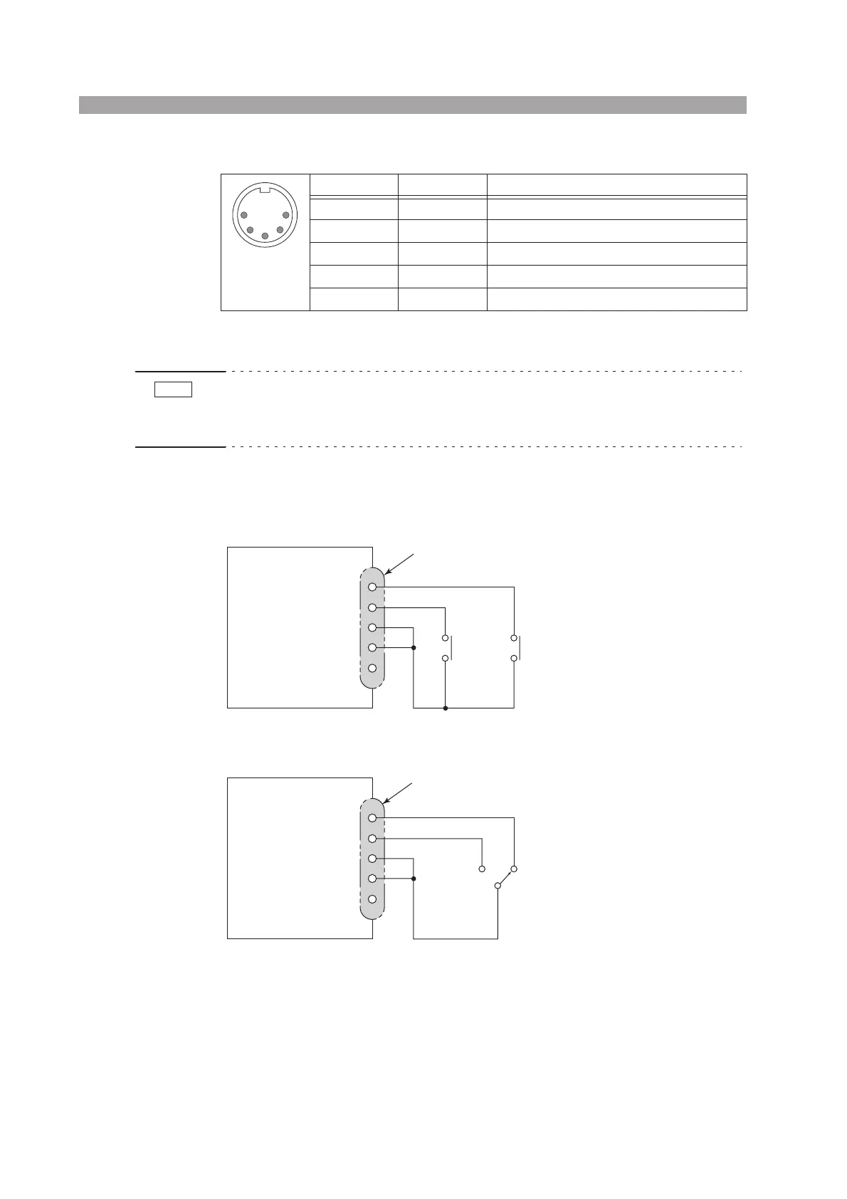
REMOTE connector pin configuration
• The configuration of the REMOTE connector pin numbers are based on DIN
Standards. Please note that the pins are not arranged by pin number.
• If the REMOTE connector pin 3 is at level L, the tester switches from front panel
control to remote control.
Configure the control circuits so that pins 2 and 3 connect externally.
Control circuit example
Fig. 6-2 Example: Circuit 1
Fig. 6-3 Example: Circuit 2
Logic elements, transistors, photocouplers, or other elements may take the place of
contacts in Fig. 6-2. Fig. 6-3 shows one example.
Viewed
from the
panel face
Pin number Signal name Description
1 RSV Leave this pin unconnected.
2 COM Common terminal
3 ENABLE Enables remote control at level L.
4 START Testing begins at level L.
5 STOP Stops testing at level L.
In this example, controlling
the START and STOP con-
tacts lets you operate the
tester in the same way as from
the front panel.
In this example, setting the
contact to the NO position
invokes a TEST state; return-
ing it to the NC position stops
testing.
1
2
3
4
5
NOTE
TOS8030
5
4
3
2
1
REMOTE connector
COM
START
STOP
TOS8030
5
4
3
2
1
COM
NO NC
REMOTE connector