EasyManua.ls Logo

Kinco CD620 - Page 59

Kinco CD620
133 pages
Print Icon
To Next Page IconTo Next Page
To Previous Page IconTo Previous Page
Loading...
59
gear 0 in mode -4
d3.35
Gear_Divider
Denominator of electronic
gear 0 in mode -4
1000
1~32767
Parameters for electronic gear ratio are used to set the numerator and denominator of electronic gears when
the driver operates in mode -4.
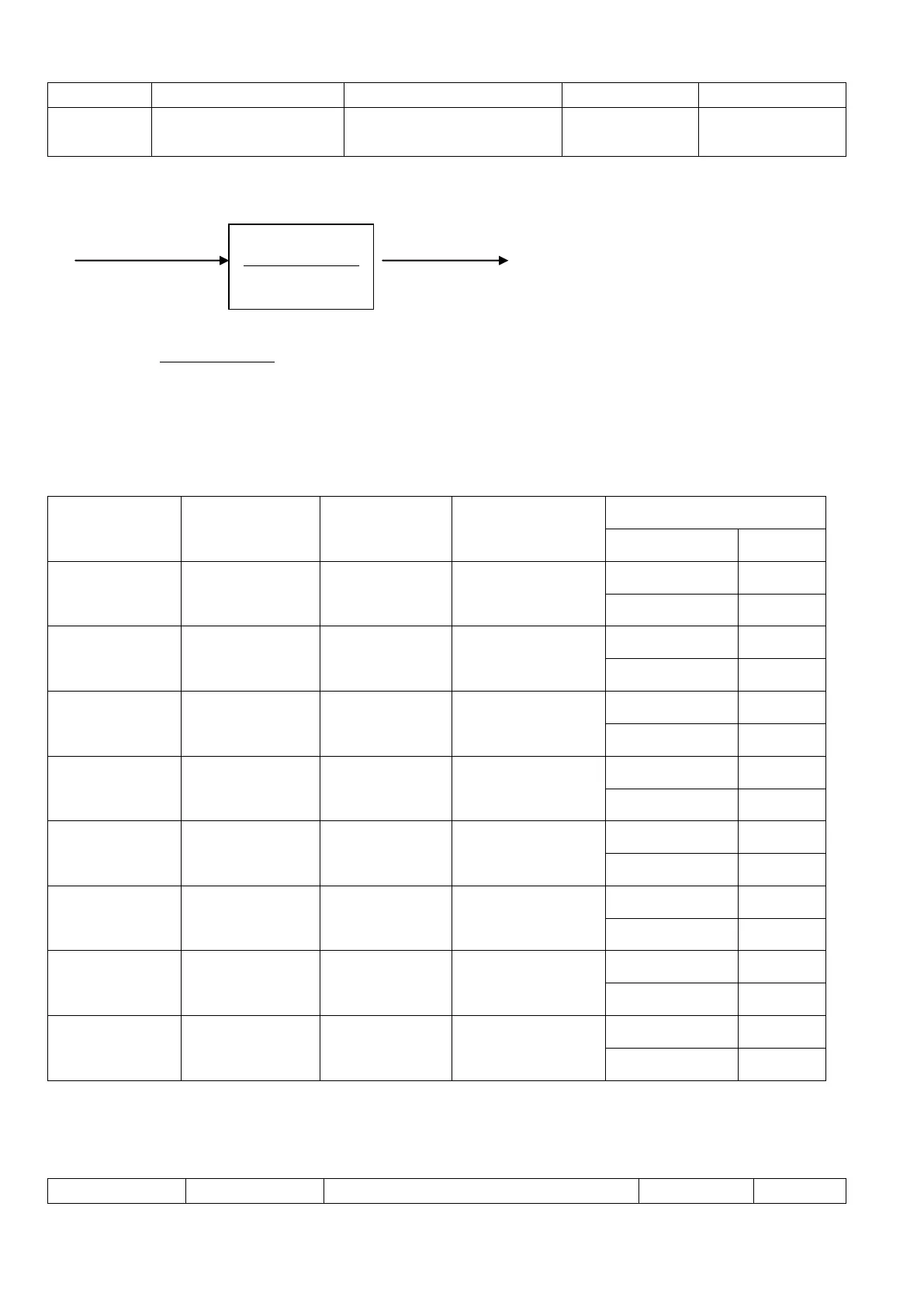
Command pulse input Command pulse output
F1 F2
Namely: F2=
DividerGear
FactorGear
_
_
* F1
If the electronic gear ratio is 1:1, 10000 pulses are inputted externally (the resolution of encoders is 2500
PPR, quadruple), and the motor turns a circle. If the electronic gear ratio is 2:1, 10000 pulses are inputted
externally, and the motor turns two circles.
Multi electronic gears can be defined by DDIN with function Multi DinX as shown in following table.
Multi Din 2
Multi Din 1
Multi Din 0
Descriptions
Parameter
Name
Address
0
0
0
Electronic gear 0
Gear_Factor 0
25080110
Gear_Divider 0
25080210
0
0
1
Electronic gear 1
Gear_Factor 1
25090110
Gear_Divider 1
25090210
0
1
0
Electronic gear 2
Gear_Factor 2
25090310
Gear_Divider 2
25090410
0
1
1
Electronic gear 3
Gear_Factor 3
25090510
Gear_Divider 3
25090610
1
0
0
Electronic gear 4
Gear_Factor 4
25090710
Gear_Divider 4
25090810
1
0
1
Electronic gear 5
Gear_Factor 5
25090910
Gear_Divider 5
25090A10
1
1
0
Electronic gear 6
Gear_Factor 6
25090B10
Gear_Divider 6
25090C10
1
1
1
Electronic gear 7
Gear_Factor 7
25090D10
Gear_Divider 7
25090E10
The default value of Gear_Factor and Gear_Divider are 1000.
2. Parameters for pulse mode selection
Table 7-2 Parameters for pulse mode selection
Numeric
Variable Name
Meaning
Default
Range
DividerGear
FactorGear
_
_

Table of Contents

Other manuals for Kinco CD620

Related product manuals