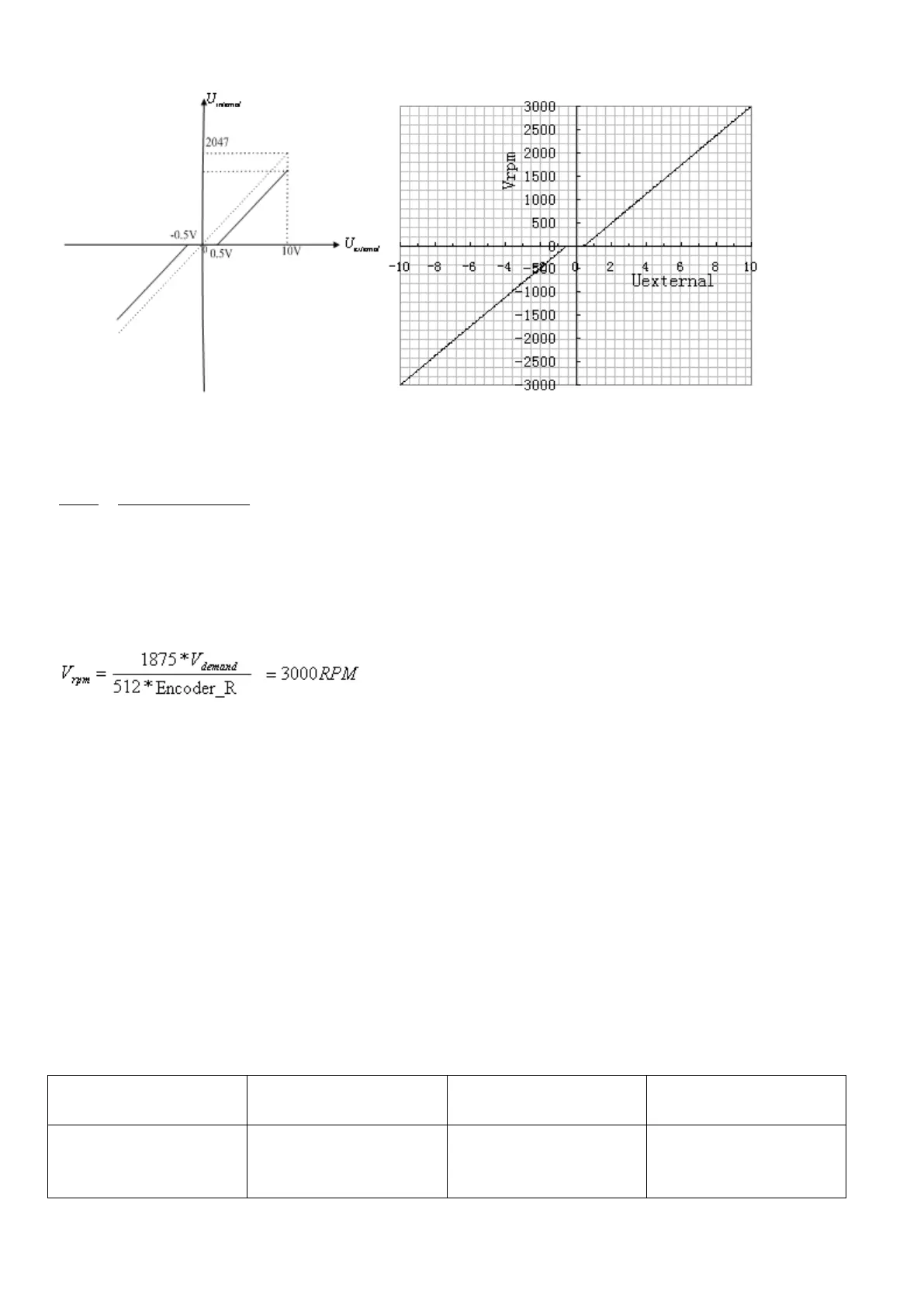
Fig. 7-10 Schematic diagram of Example 7-4
Calculate
according to the offset voltage and dead zone voltage that require settings:
2047
10 10
filter
shift dead
U
v v U U
(In this example,
.5, and
)
Result:
=1944
Calculate
according to the required speed :
, (Encoder_R:10000 inc/r)
Result:
Calculate
according to
and
:
*
demand filter
V Factor U
Result:
=4213
Calculate
according to the required dead zone voltage:
8191/10 log1_ /
dead
v Ana Dead U
Result:
=410
The following changes are required on the basis of Example 7-3.
Table 7-13 Parameter settings in Example 7-4
Sets dead zone data for
external analog signal 1
Sets the proportion
between analog signals
and output speed