1: Storing all configured
parameters for the
control loop
10: Initializing all
parameters for the
control loop
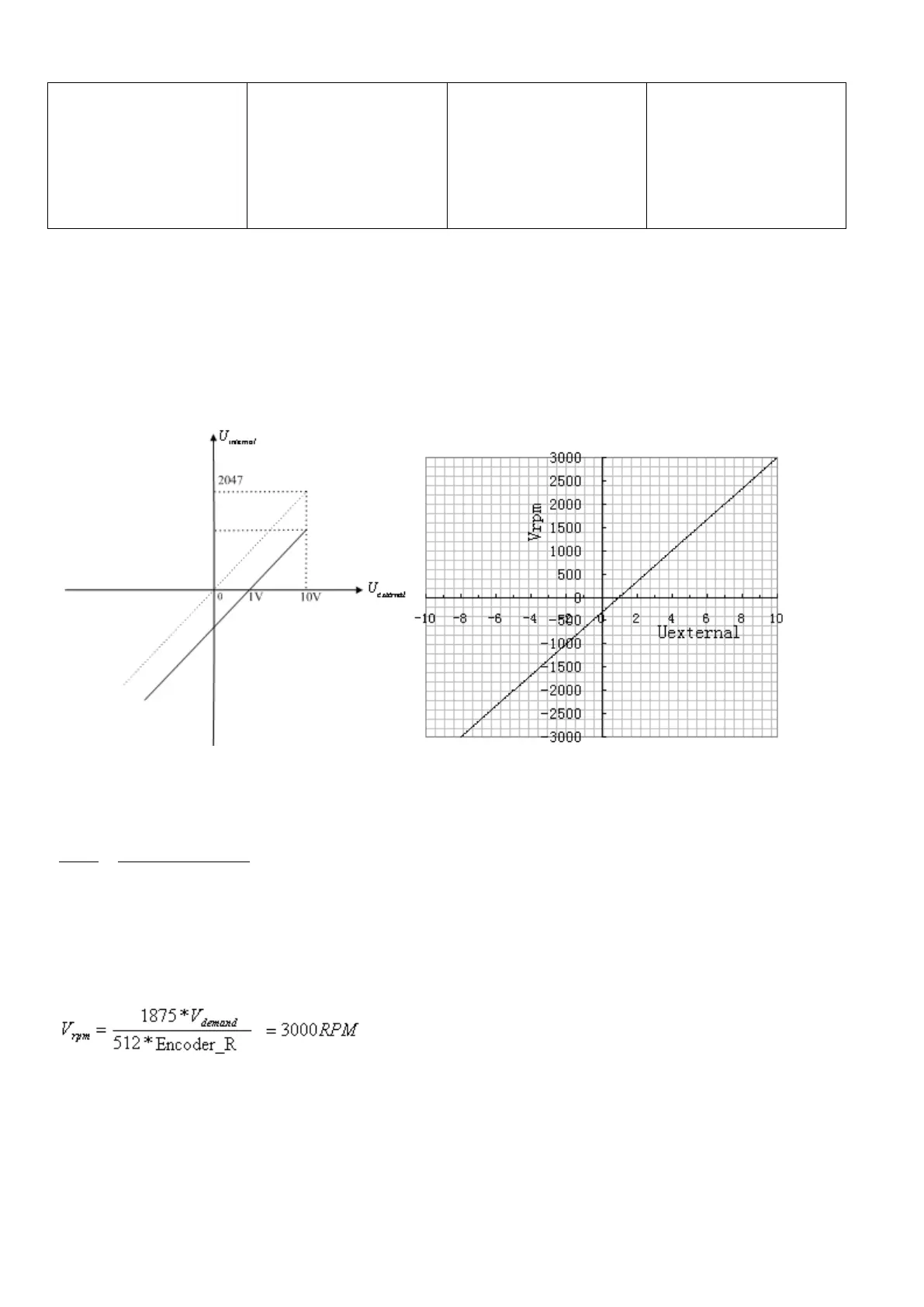
Example 7-5 Analog – speed mode (setting the offset voltage)
Requirement: The offset voltage is 1 V, that is, the speed is positive when the voltage is greater than 1 V, and
is negative when the voltage is less than 1 V. In this case, the voltage 10 V corresponds to 3000 rpm, and -9
V corresponds to -3000 rpm (in case of -10 V, the corresponding speed is less than -3000 rpm). Select analog
channel 1 (AIN1) to control the speed.
Fig. 7-11 Schematic diagram of Example 7-5
Calculate
according to the offset voltage and dead zone voltage that require settings:
2047
10 10
filter
shift dead
U
v v U U
(In this example,
, and
)
Result:
Calculate
according to the required speed :
, (Encoder_R:10000 inc/r)
Result:
Calculate
according to
and
:
*
demand filter
V Factor U