parameters for the
control loop
10: Initializing all
parameters for the
control loop
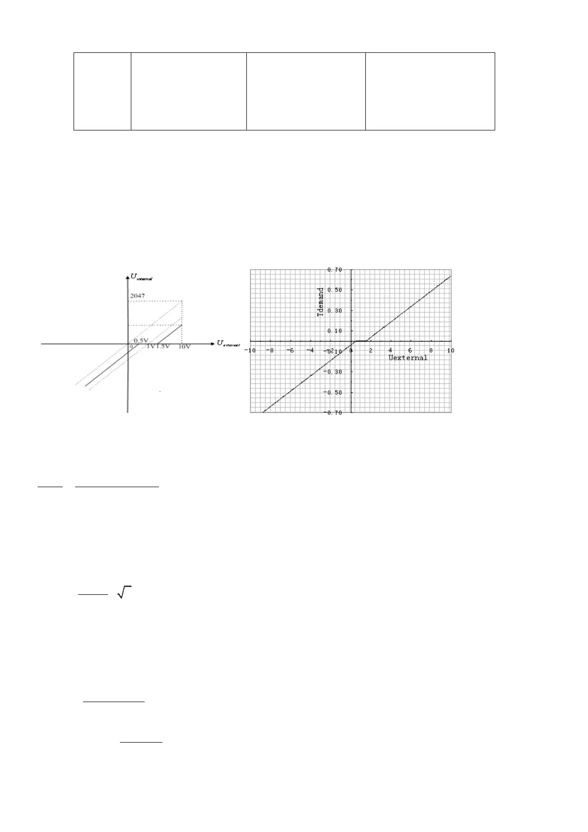
Example 7-8: Analog – torque mode (setting the dead zone voltage and
offset voltage)
Requirement: The offset voltage is 1V, and the dead zone voltage is 0.5V. The motor Kt is 0.48 Nm/A, and the
peak current of the driver is 15A. The analog input voltage 10V corresponds to 0.64Nm. Select analog
channel 2 (AIN2) to control the torque.
Fig. 7-16 Schematic diagram of Example 7-8
Calculate
according to the offset voltage and dead zone voltage that require settings:
2047
10 10
filter
shift dead
U
v v U U
(In this example,
.5, and
)
Result:
=1740
Calculate
according to the required torque
:
Result:
= 1.89
Calculate
according to
and
:
*2048*4096
*
demand
filter
I
Factor
U Ipeak
Result:
1.89
*2048*4096 606
1740*15
Factor