5-7
IGNITION SWITCHES
Refer to page 4-5 for the procedure for servic-
ing the ignition switches.
NOTE: The ignition switches will be serviced
as a complete assembly. If a switch is defec-
tive, the complete assembly must be replaced.
1. Turn off gas supply and disconnect power
to the range.
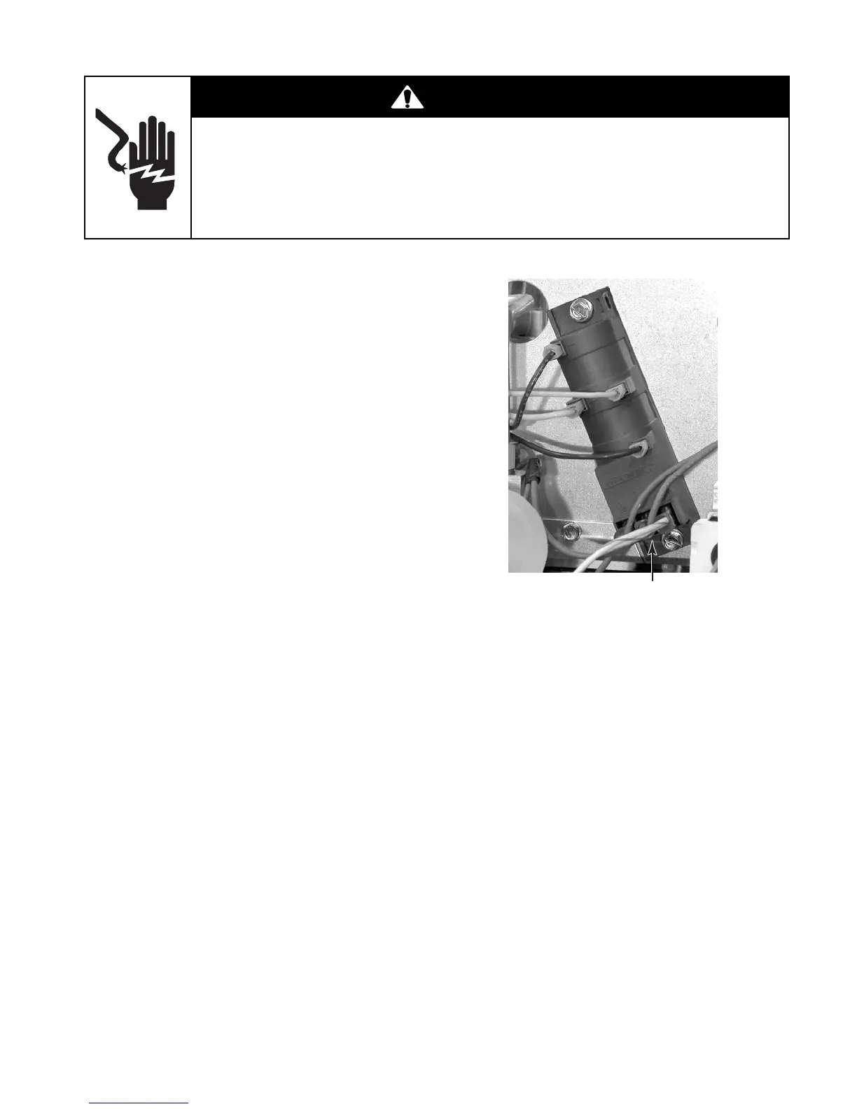
2. Locate the 2 white-blue ignition switch
wires on the spark module and disconnect
the connector from the terminal.
3. Locate the white wire coming from the
ignition switches and disconnect it from
the main harness.
4. Set the ohmmeter to the R x 1 scale.
5. Touch the ohmmeter test leads to the
white and white-blue wire connectors. With
all of the switches in the Off position, the
meter should indicate an open circuit (in-
finite ∞). When a switch is turned to the
LITE position, the meter should indicate a
closed circuit (0 Ω).
2 Wht/Blu Ignition Switch Wires
On Spark Module Terminals
WARNING
Electrical Shock Hazard
Disconnect power before servicing.
Replace all parts and panels before operating.
Failure to do so can result in death or electrical shock.