6-1
DIAGNOSIS & TROUBLESHOOTING
DIAGNOSIS
• All units that have failed during the first few
days of use should be checked for loose
connections, or miswiring.
• All checks should be made with a meter
having a sensitivity of 20,000 ohms-per-volt,
or greater.
FAILURE/ERROR DISPLAY CODES
• All diagnoses of this range must begin with a
normal check of the line voltage, blown fuses,
and failed components.
F01
1. Unplug range or disconnect power.
2. Check sensor connection.
3. Measure sensor resistance (1080 at 70
°
F[21
°
C]. Add 2 per 1
°
F[.55
°
C].)
4. If resistance is not valid, replace sensor.
5. If sensor resistance and connections are good, check for pinched sensor wires from the control to the sensor.
6. If sensor resistance and connections are good, then check for welded-closed relays on the control.
F02
1. Unplug range or disconnect power.
2. With the control powered down, check continuity across P4-1 or P4-2 (both are L1) and the following connections:
F04
• If both displays show a failure:
- Check main control harness.
- Check LS and RS connectors.
- Replace main control.
- Check P9 connector on right control.
- Replace right control.
- Check P9 connector on left control.
- Replace left control.
• If only right display shows failure:
- Check main control harness.
- Check RS connector.
- Check P9 connector on right control.
- Replace right control.
• If only left display shows failure:
- Check main control harness.
- Check LS connector.
- Check P9 connector on left control.
- Replace left control.
F05
1. Unplug range or disconnect power.
2. Check the Latch Assembly:
- Check latch arm pivot joint, arm/motor connection, plunger and plunger spring.
3. Check the Latch Motor:
- Check for firm electrical connections.
- Disconnect the two wires from the motor and measure the resistance of the motor. The resistance
4. Check the Latch Switch:
- Disconnect it and use a continuity tester:
5. Check Door Open/Closed Switches:
- Disconnect it and use a continuity tester:
Door open = switch open, continuity should read infinite.
Door closed = switch closed, continuity should read 0 Ω.
6. Check power and element connections.
F06
1. Unplug range or disconnect power.
2. Replace control.
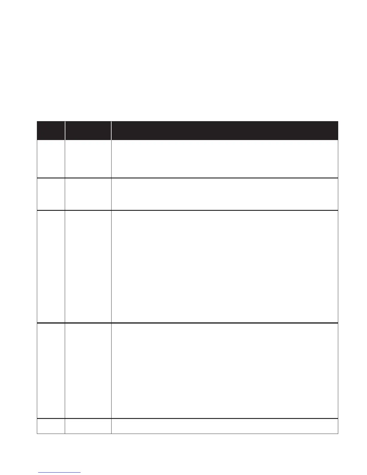
FAULT
CODE
CODE
EXPLANATION
RECOMMENDED REPAIR PROCEDURE
Temperature sensor
opened
Welded element
relays
Communication
error
Door or latch
problems
Electronic control
malfunction
P5-1 for Broil element
P5-3 for Bake element
P5-4 for Convection element
Unplug range or disconnect power.
should be approximately 2450. If the motor is open or shorted, it should be replaced.
Door latched = switch closed, continuity should read 0 Ω.
Door unlatched = switch open, continuity should read infinite.