
 To Next Page


C
Christina RussellSep 1, 2025
What to do if the operation panel is not connected on Koden Marine Radar?
- JJuan ObrienSep 1, 2025
If the operation panel is not connected on your Koden Marine Radar, reconnect the operation panel connector.

What to do if the operation panel is not connected on Koden Marine Radar?
If the operation panel is not connected on your Koden Marine Radar, reconnect the operation panel connector.
What could cause a magnetron current issue on Koden MDC-2240?
A magnetron current issue on your Koden Marine Radar could be caused by a blown TXHV fuse or the magnetron reaching the end of its life. Check the TXHV fuse and replace the magnetron if necessary.
What causes a magnetron heater current problem on Koden Marine Radar?
A magnetron heater current problem on Koden Marine Radar may be due to a magnetron malfunction or a transmitter PCB malfunction. Test the magnetron and transmitter PCB for proper operation.
What causes high voltage on the magnetron in Koden MDC-2240?
If there's high voltage on the magnetron in your Koden Marine Radar, it could be due to a blown TXHV fuse or a transmitter PCB malfunction. Inspect the TXHV fuse and transmitter PCB for faults.
What causes 'No azimuth signal' on Koden MDC-2240 Marine Radar?
The absence of an azimuth signal on your Koden Marine Radar may be due to a blown motor fuse or a malfunction in the transmitter PCB. Replace the motor fuse and check the transmitter PCB.
Why am I getting 'No heading line signal' on my Koden MDC-2240?
A 'No heading line signal' error on your Koden Marine Radar can occur if the motor fuse is blown or the transmitter PCB is malfunctioning. Replace the motor fuse and verify the transmitter PCB functionality.
What should I do if there is no trigger signal on Koden Marine Radar?
If your Koden Marine Radar has no trigger signal, inspect and repair the transmitter PCB, as the cause is a transmitter PCB malfunction.
Provides an overview of the operation manual, including safety symbols and their meanings.
Details safety guidelines for radar operation, covering aerial, electromagnetic disturbance, and high voltage.
Instructions for safe disposal of device components and overview of the radar system's key features.
Procedure to disengage alarm detection function when heading or speed signals are not received.
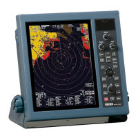
Details the various elements displayed on the radar screen, including ranges, markers, and indicators.
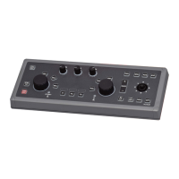
Identifies and describes the layout of buttons and knobs on the MDC-2500 and MDC-2200 control panels.
Explains the function of individual keys and knobs: DAY/NIGHT, EBL, RAIN, SEA, GAIN, VRM, RANGE, ENH.
Explains the function of individual keys: MENU, ACQ, ENT, POWER, STBY/TX, EBL, OFFSET, BRILL, F1, F2.
Explains the function of individual keys: F3, PANEL, PI, VRM, SP/LP, OFF CENT, MODE, OFF, Joystick.
Instructions for turning the radar system on and off, including power re-entry timing.
How to adjust the brightness of the display screen and control panel dimmer using specific keys and knobs.
Procedures for initiating and halting radar transmission using the STBY/TX key.
How to adjust the radar's observing range (zoom in/out) using the RANGE keys.
Guide on using the GAIN knob to optimize target visibility based on observing conditions.
Using the SEA knob to suppress sea clutter and improve target detection, especially at short ranges.
Using the RAIN knob to suppress rain/snow clutter for clearer target observation in adverse weather.
How to adjust pulse length for optimal target detection based on resolution and gain.
Using the ENH function to improve the visibility of specific targets on the radar display.
Using VRM1 and VRM2 to measure the distance of targets from the ship's position.
Using EBL1 and EBL2 to measure the bearing of targets from the ship or an optional point.
Using Parallel Index lines to measure distance and bearing, and setting line numbers.
Setting up Parallel Index lines for the MDC-2500 model, including line number and display.
Adjusting the interval and bearing of PI lines, and rotating the EBL knob.
Using the offset function to change the origin point for measuring distance and bearing between two targets.
Changing echo colors for day/night modes and temporarily hiding the heading line.
Moving the own ship's position on the screen for a broader view or specific orientation.
How to choose between different display modes like Head Up, Course Up, and North Up.
Explains the Course Up and North Up display modes for navigation and chart consultation.
Explains the differences between relative motion (RM) and true motion (TM) display modes.
How to reset the true motion display position to its initial state.
Introduces ATA/EPA functions for target acquisition, plotting, and collision avoidance.
Step-by-step guide for manually acquiring targets using the joystick and acquisition key.
Procedures for selecting and deleting individual acquired targets from the system.
How to clear all tracked targets from the system via the menu.
Configuring the system for automatic target acquisition within a specified area.
Setting up the parameters (bearing, range, width, depth) for the auto acquisition area.
Configuring the display of detailed information for acquired targets on the lower screen.
Configuring vector length, mode, CPA, TCPA, and manual acquisition limits.
Steps for operating the Electronic Plotting Aid (EPA) to track target movement.
How to correct the latest tracking point for EPA data.
Explains the different symbols used for ATA and EPA target acquisition and alarm states.
How to assign functions to F keys for easier operation and access to features.
Creating custom shortcut menus accessible via function keys for quick access to functions.
Methods for outputting position data via TLL sentence for cross cursor or marks.
How to display, delete, and select items within the main and sub-menus.
How to confirm settings and access more detailed menu options.
Configuration options within the MARKER menu, including range rings and bearing settings.
Setting bearing modes (relative/true) and configuring parallel index lines.
Customizing how the cross cursor and its associated data (bearing, range, lat/lon) are displayed.
Setting range units for VRM/PI, display options for stern marker, cursor shape, and tracking cursor.
Managing HU bearing interlocking, VRM/EBL intersection display, and bearing scale options.
Selecting display formats for bearing, heading line blinking, guard lines, and own ship outline/profile.
Creating and displaying a profile of the own ship using multiple lines.
Configuration settings for radar echo display, including mode, trails, color, and zoom.
Setting display modes (H UP, C UP, N UP with RM/TM) and configuring target trails.
Explains relative and true trail display, including collision prospects and visual cues.
Configuring trail color, shape, sustain range, time keep, and true motion input sensor.
Setting relative mode criteria, trail detection level, and interference rejection.
Adjusting echo and background colors for day/night modes and using zoom for cursor position.
Setting true motion reset position, fixed image, sector scan, and rotation parameters.
Configuring full screen display and own ship position offset settings.
Navigation menu settings, including stabilization base, tide compensation, and vector display.
Configuring vector display modes, navline functions, and detection settings.
Alarm settings, including guard zone, CPA/TCPA limits, and buzzer configurations.
Setting up a sector alarm area (guard zone) for target detection and alerts.
Configuring CPA/TCPA limits, buzzer sounds, and Alarm 1 settings.
Setting the specific area for Alarm 1, including shape and size.
Configuring Alarm 1 detection mode/level and setting up Alarm 2.
Deleting Alarm 2 data, selecting detection methods, setting levels, and inputting/editing data.
How to silence an active alarm sound.
Selecting ATA or EPA function, and performing manual target acquisition.
Deleting all targets, setting manual acquisition numbers, auto acquisition, and target ID display.
Configuring the format for displaying ATA/EPA information (RNG/BRG or LAT/LON).
Activating AIS display and configuring how target IDs are shown on screen.
Selecting targets, setting detection areas, and configuring lost/sleep ship displays.
Setting up SART/BASE target symbols, auto acquisition rings, and understanding AIS symbols.
Chart menu settings for display, waypoints, routes, and marks.
Turning chart display on/off and inserting C-MAP chart cards.
Setting up and managing tracks for own ship, ATA, and AIS targets.
Setting track memory intervals, deleting tracks, setting waypoints/routes, and displaying marks.
Deleting mark data, displaying lines to marks, selecting mark shapes, and inputting marks.
Inputting/deleting marks by cursor, editing marks, displaying all marks, and selecting chart types.
Adjusting detailed chart display settings and performing position compensation.
Selecting and using functions for producing coastlines and displaying GPS buoys.
Functions for displaying buoy IDs, water temperature, and block data.
Settings for displaying various data on the upper and lower screens.
Configuring display items for DISP1, DISP2, DISP3, and protecting menu settings.
Initial setup options, including tuning methods and function key assignments.
Configuring STC curve, Main Bang Suppression, and assigning functions to F, RAIN, SEA, GAIN keys.
Adjusting radar image parameters like Gain, STC, ATA target level, and Video mode.
Configuring FTC, Main Bang Suppression, target level, ATA performance, and video modes.
Adjusting brilliance for various screen elements like radar echo, trails, charts, and menus.
Performing built-in tests for alarm, ATA, panel, and system diagnostics.
Executing panel tests, monitoring input ports, and diagnosing ATA/AIS board status.
Displaying status of the antenna unit, including voltage, current, and communication.
Configuring inter-switch connections, antenna location, echo offset, and motor speed.
Hiding/showing information on screen and activating ferry mode for specific navigation scenarios.
Changing length units from meters to feet for various display items.
Reading out and saving system setup items for backup and recovery.
Loading/saving settings, system programs, ATA/AIS programs, and past data.
Information on the availability of the Preset Load function.
Provides a visual summary of menu structures and settings.
Detailed configuration mapping for various menu items.
Detailed configuration mappings for menu items.
Additional menu configuration mappings, including I/O settings.
Final menu configuration mappings, including system and option settings.
More menu configuration mappings, covering BITE and ANTENNA menus.
Final menu configuration mappings, including OPTION and INITIAL menus.
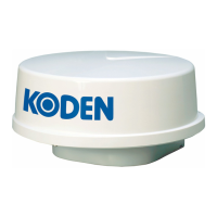
Technical details of the radar antennas, including type, length, beam width, and power.
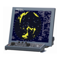
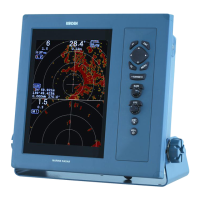
Technical details of the display unit, including screen size, resolution, and features.
Lists standard and optional configuration items included with the radar system.
Provides physical dimensions and weight of the MDC-2200 and MDC-2500 series units.
Basic explanation of how radar works, including transmission, reception, and target detection.
Explains the concept of side lobes in radar antenna patterns and their effects.
Defines beam width and its importance in radar performance.
Discusses factors affecting target reflection strength and radar detectability.
Explains radar shadow effects caused by obstructions near the antenna.
Describes causes and types of false images that can appear on the radar display.
Further explanation of false images, including duplicate targets and side lobe effects.
Discusses radar interference and the system's capability to reduce it.
 General
| Type | Color LCD |
|---|---|
| Power Supply | 24 V DC |
| Transmitter Output Power | 4 kW |
| Power Output | 4kW |
| Display Size | 10.4 inches |
| Frequency | 9410 MHz |
| Display | Color LCD |
| Antenna Rotation Speed | 24 rpm |