5-64 Accessory Troubleshooting
TP-5672 11/95
Yes
Yes
No
Yes
YesNo
No
No
No
Yes
No
No
No
Yes
Yes
Yes
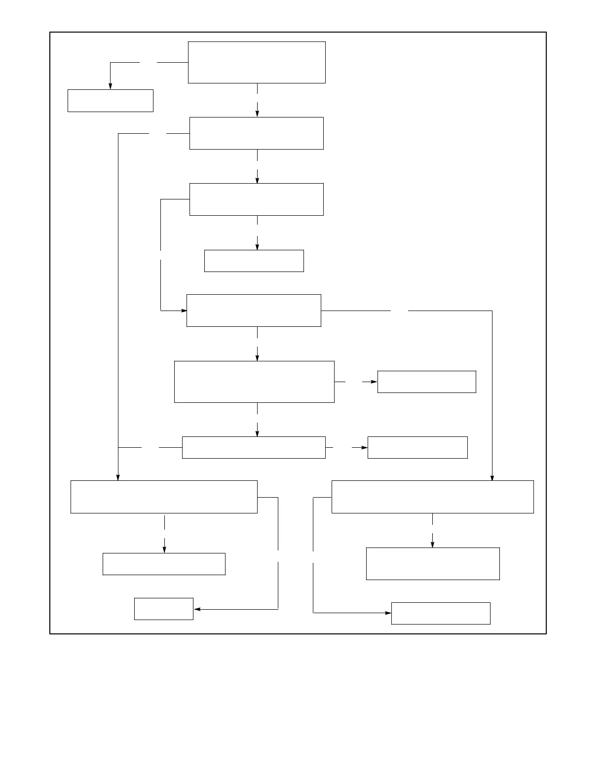
Is there between 12 and 30 vdc
between terminals TD-DC1-23
and TB-DC1-34 of the power
supply board?
Is there between 12 and 30 vdc
between pins P11-8 and P11-2
of plug P11?
Is there between 12 and 30 vdc
between pins P17-1 and P17-9
of plug P17?
Is there between 12 and 30 vdc
between terminals 42A and 2 of
the dry contact circuit board?
Replace the power
supply board.
Replace the load-shed
buffer board.
Replace the load-shed
circuit board.
Is there 5 vdc between pins P11-1
and P11-5 of plug P11?
Replace the load-shed
circuit board.
Check the continuity of the ribbon cable
between plugs P10 and P11. Does the cable
have any open leads or bent or broken pins?
Replace the ribbon cable
between plugs P10 and P11.
Replace the
logic board.
Check the wiring harness between the load-shed
buffer board and the load-shed circuit board. Are
there any open leads or bent or broken pins?
Replace the wiring harness
between the load-shed buffer
board and the load-shed board.
Replace the load-shed
buffer board.
Does grounding each dry contact
terminal energize the appropriate
relay (Grounding 3 energizes relay 3,
grounding 4 energized relay 4. etc.)?
Figure 5-71. Troubleshooting—Option DD-35-N, Load-shedding contacts