4-24 Controller Troubleshooting
TP-5672 11/95
Source Monitors
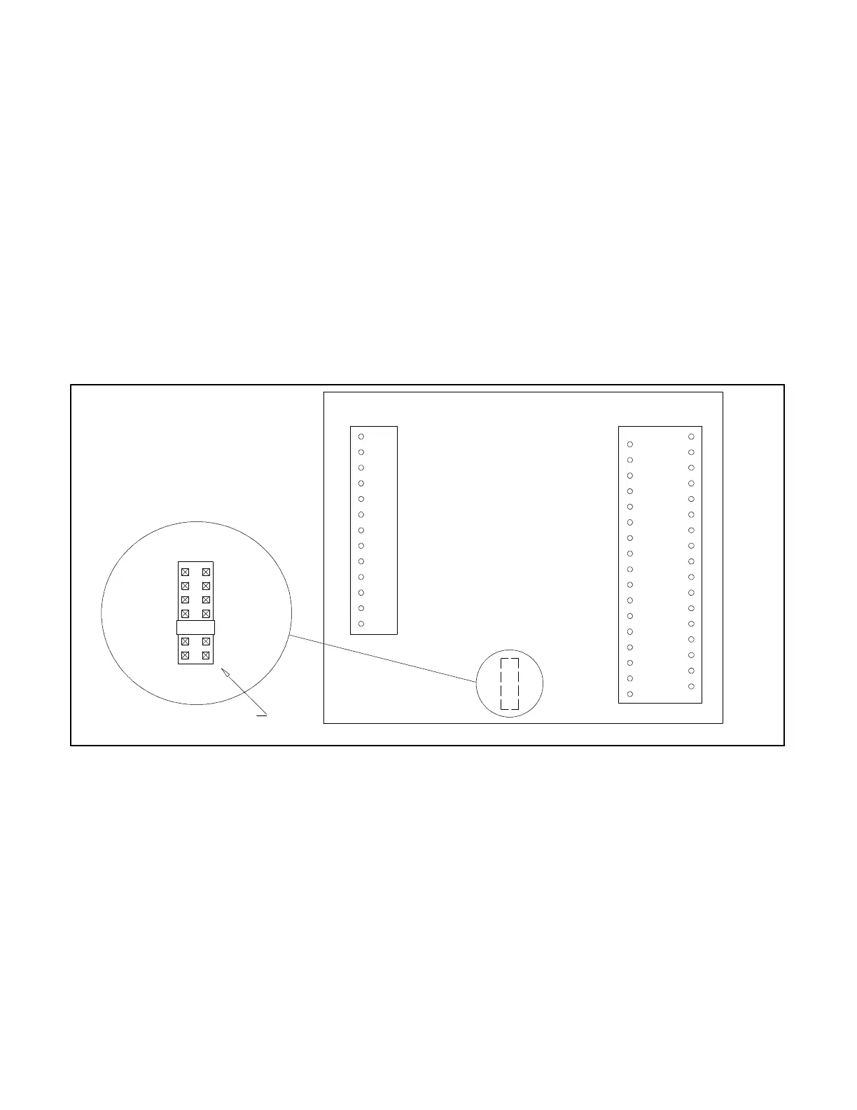
The Source Monitor Phase Sequencer accessory
DD-34-Z providessourcemonitoringfor both thenormal
and emergency sources. The features include phase
rotation and anti-single phasing protection. This option
must be used in conjunction with DD-05-K in order to
provide three-phase source monitoring on the
emergencyside. Thisaccessoryneedstobeenabledby
installing the PHASE SEQUENCER jumperonthemain
logic board. See Figure 4-15. A wiring diagram for this
option is in Figure 4-21.
The Voltage/Frequency Sensing accessory, DD-34-J,
provides source monitoring for both the normal and
emergency sources. This accessory senses an
overvoltage condition for all normal source phases, an
over/underfrequency condition on one normal source
phase, and an overfrequency and overvoltagecondition
on one emergency source phase. This accessory is
enabled by installing the VOLT/FREQ jumper on the
main logic board. See Figure 4-15. See Appendix B,
Figure B-4 for the emergency source voltage trip point
setting limits and factory settings. A wiring diagram for
this accessory is in Figure 4-22.
The three-phase emergency source sensing accessory
DD-05-K provides source monitoringfor the emergency
source. Thefeatures includeoverfrequency sensingfor
one phase of the emergency source and
over/undervoltage sensing for all three phases of the
emergencysource. Thisaccessoryneedstobeenabled
by installing the PHASE SEQUENCER jumper on the
mainlogic board. See Figure 4-15. Figure 5-3 shows a
wiring diagram for this option.
17
1
TB--DC1TB--AC1
2
3
4
5
6
7
8
9
10
11
12
13
14
15
16
18
19
20
21
22
23
24
25
26
27
28
29
30
31
32
33
34
NA
NB
NC
EA
EB
EC
LA
LB
LC
NAS
NCS
EAS
ECS
MICROCONTROLLER
MANUAL
TIME
PLANT
VOLT/
PHASE
IN--PHASE
OVRIDE
DELAY
EXER
FREQ
SEQUENCER
MONITOR
Programming shunt (294634)
must be installed to activate accessory
560455
OFF
DELAYS
Figure 4-21. Wiring Diagram—Source monitor phase sequence, option DD-34-Z