4-21
Controller Troubleshooting
TP-5672 11/95
Shunt Jumper-Controlled Options
Jumpers installedintheshunt-jumpersocketJP1 on the
main logic board control the following options.
D Extended Time Delays—DD-100-B
D Plant Exerciser—DD-23-C, DD-23-D, and
DD-23-G
D Voltage/Frequency Sensing—DD-34-J
D Phase Sequencer—DD-34-Z and DD-05-K
D In-phase Monitor—DD-34-A
D Off Delays
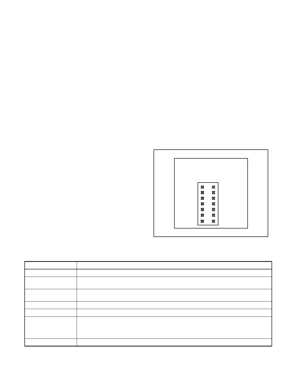
See Appendix B Figure B-9 to locate JP1. See
Figure 4-15 to locate option shunt jumper locations on
JP1. Programming Index 11 displays installed control
options status as enabled or disabled. Figure 4-16
describes the options in Index 11.
To add/remove shunt-jumper controlled options:
1. Add/remove shunt-jumpers across the terminals
nextto thename of the optionon JP1and shownin
Figure 4-15. Do not remove the MANUAL
OVERRIDE jumper.
2. Go to Index 20 and press Menu Down and look for
OPTIONS LOCK? NO. If the question does not
appear, the options are locked. Go to step 3.
Otherwise, lock the options:
a. Answer the question with YES then ENTER.
The controller briefly displays ENTRY
ACCEPTED.
b. Press RESET MENU and then ENTER to store
the setpoints. The controller briefly displays
STORE SET--POINTS. Theoptions willremain
locked when the controller powers back up the
next time.
3. Power down the controller by disconnecting the
inline disconnect plug P1.
4. Waitaminimumof1 minutethenreconnectplugP1
to power up the controller.
5. Check Index 11. YES should appear only after the
Index 11 listing of all options with installed shunt
jumpers.
To troubleshoot shunt jumper-controlled options see
Figure 4-17 or Figure 4-18.
NOTE
When the options are not locked the controller does not
checkJP1uponpoweruptodetermineoptionstatus,but
rather reads the setpoints stored before power was
interrupted.
560451
OVRIDE
DELAY
EXER
FREQ
SEQUENCER
MONITORIN-PHASE
PHASE
VOLT/
PLANT
TIME
MANUAL
Main Logic Board
OFF
DELAYS
Figure 4-15. Shunt-jumper socket JP1
Control Option Description
INPHASE MON Shows Inphase Monitor enabled (Yes) or disabled (No).
PHA SEQ/LOSS Shows Source-Phase-Sequence enabled (YES) or disabled (NO). (Transfer Switch contactor lug
connections must be properly phased ABC in order for the source to be acceptable).
NORM & EMER Shows sensing enabled (YES) or disabled (NO) of overvoltage, undervoltage, overfrequency,
underfrequency for both the normal source and the emergency source.
PLANT EXER Shows generator set/system exerciser enabled (YES) or disabled (NO).
TD EXTENDED Shows extended time delay enabled (YES) or disabled (NO).
MAN OVERRIDE Shows manual override enabled (YES) or disabled (NO). Enabled manual override (YES) allows
automatic transfer to an available source when connected source fails. Transfer time delays will
be bypassed. Disabled manual override (NO) causes the logic board to wait for manual operation.
The logic board will not automatically seek available source.
OFF DELAYS Shows time delay off to normal and off to emergency are enabled (YES) or disabled (NO).
Figure 4-16. The installed control options as they appear on the LCD