4-14 Controller Troubleshooting
TP-5672 11/95
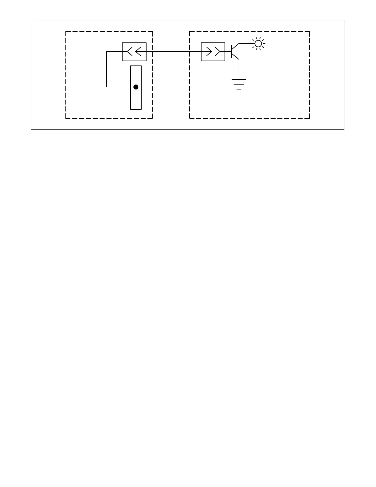
Fault LED
TB-DC1-8
P2-7 P2-7
Main Logic Board
Power Supply Board
560449
Figure 4-9. Wiring Diagram—Fault #1 or Fault #2 message
Fault #1 Or Fault #2 Message
The external fault function can be used to identify a
problemwith the emergencypowersystem,orasupport
device of the emergency power system. A dry relay
contactcanbeusedtosignalafault,suchasaTenRelay
DryContact Kit, soldasanaccessorywiththegenerator
set.
NOTE: The contact kit must be a dry contact, the logic
controller supplies its own voltage source.
The fault messages are used to monitor accessory
components. AfaultmessageappearsontheLCDwhen
an accessory is grounding the pin to which it is
connected. See Figure 4-9.
1. If a FAULT#1messageappearsonthe LCD,check
TB-DC1-8.
a. IfthereisanaccessoryconnectedtoTB-DC1-8,
disconnect the accessory. Press the RESET
MENUkey. If themessagedisappears,thelogic
board is performing correctly. The FAULT #1
messageiscausedbytheconnectedaccessory.
b. If there is not an accessory connected to
TB-DC1-8, remove power from the logic board
and disconnect the P2 ribbon cable connector
from the power supply board. Using an
ohmmeter, connect one test lead to P2-7 on the
powersupplyboard. Connect the othertest lead
to TB-DC1-34. If the resistance is low, replace
thepowersupply board.If theresistanceishigh,
replace the logic board assembly.
2. If a FAULT#2messageappearsonthe LCD,check
TB-DC1-11.
a. If there is an accessory connected to
TB-DC1-11, disconnect the accessory. If the
message disappears, then the logic board is
performing correctly.
b. If there is not an accessory connected to
TB-DC1-11, remove power from the logic board
and disconnect the P2 ribbon cable connector
from the power supply board. Using an
ohmmeter, connect one test lead to P2-8 on the
powersupplyboard. Connect the othertest lead
to TB-DC1-34. If the resistance is low, replace
thepowersupply board.If theresistanceishigh,
replace the logic board assembly.