5-15
Accessory Troubleshooting
TP-5672 11/95
Relay Auxiliary Dry Contacts
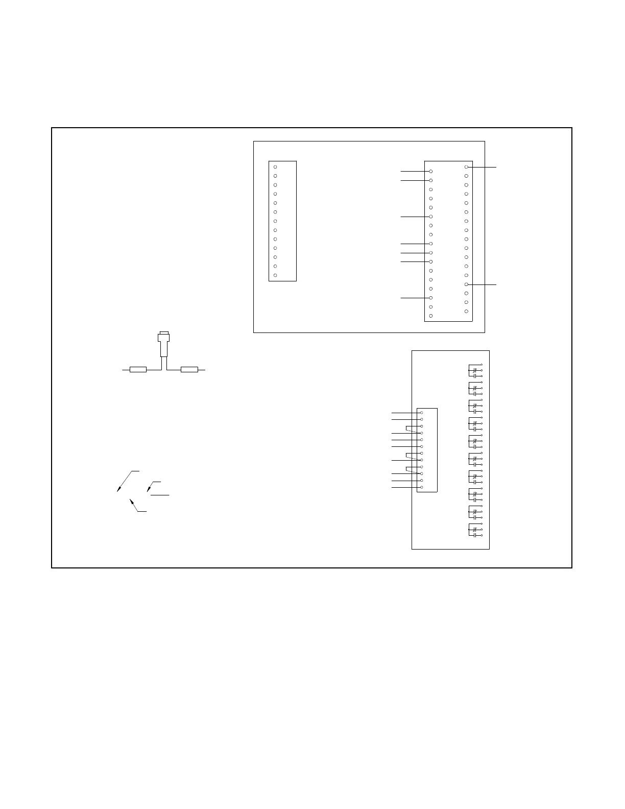
Auxiliary Dry Contacts option DD-14-G provides ten
contactsfor remote indication.The contacts are ratedat
10 amperes and 125 volts AC. This accessory indicates
normal and emergency contactor positions, normal and
emergency source availability, control not in automatic,
programmodenot in off, andsystemalert. DD-14-Gcan
be fitted to a transfer switch alone or with up to two
additional auxiliary dry contact accessories. Figure 5-16
contains a wiring diagram for DD-14-G.
ATS not in auto
Program switch “not in off”
System alarm
System alarm
Emergency position
Normal position
Emergency available
Emergency available
Normal available
Normal available
114--DCK--K10
101--DCK--K9
Shown De-energized
4FU--R--142
TBDC1--32--132
TBDC1--26--126
TBDC1--18--118
TBDC1--28--128
TBDC1--27--127
TBDC1--19--119
TBDC1--1--101
TBDC1--14--114
J
J
J
DCK
K1
K2
K3
K4
K5
K6
K7
K8
K9
K10
142--DCK--42A
SPLICE
4FU
TBDC1--23--123
SPLICE
BK R
DCK--K6--127
DCK--K1--126
4FU--BK--123
DCK--K7--119
DCK--K3--118
DCK--2--132
DCK--K5--128
MICROCONTROLLER
TB--DC1TB--AC1
34
33
32
31
30
29
28
27
26
25
24
23
22
21
20
19
18
16
15
14
13
12
11
10
9
8
7
6
5
4
3
2
1
17
ECS
EAS
NCS
NAS
LC
LB
LA
EC
EB
EA
NC
NB
NA
42A
2
K1
K2
K3
K4
K5
K6
K7
K8
K9
K10
Wire Code Example
S10--13—201
Device Name
Wire Number
Device Terminal
Number
5604521
Figure 5-16. Wiring Diagram—Option DD-14-G, Auxiliary Dry Contacts