5-16 Accessory Troubleshooting
TP-5672 11/95
Additional auxiliary dry contact accessories are
describedbelow. Wiring diagrams for theseaccessories
are in Figure 5-17 to Figure 5-24. Refer to Figure 5-25
for the troubleshooting flowchart.
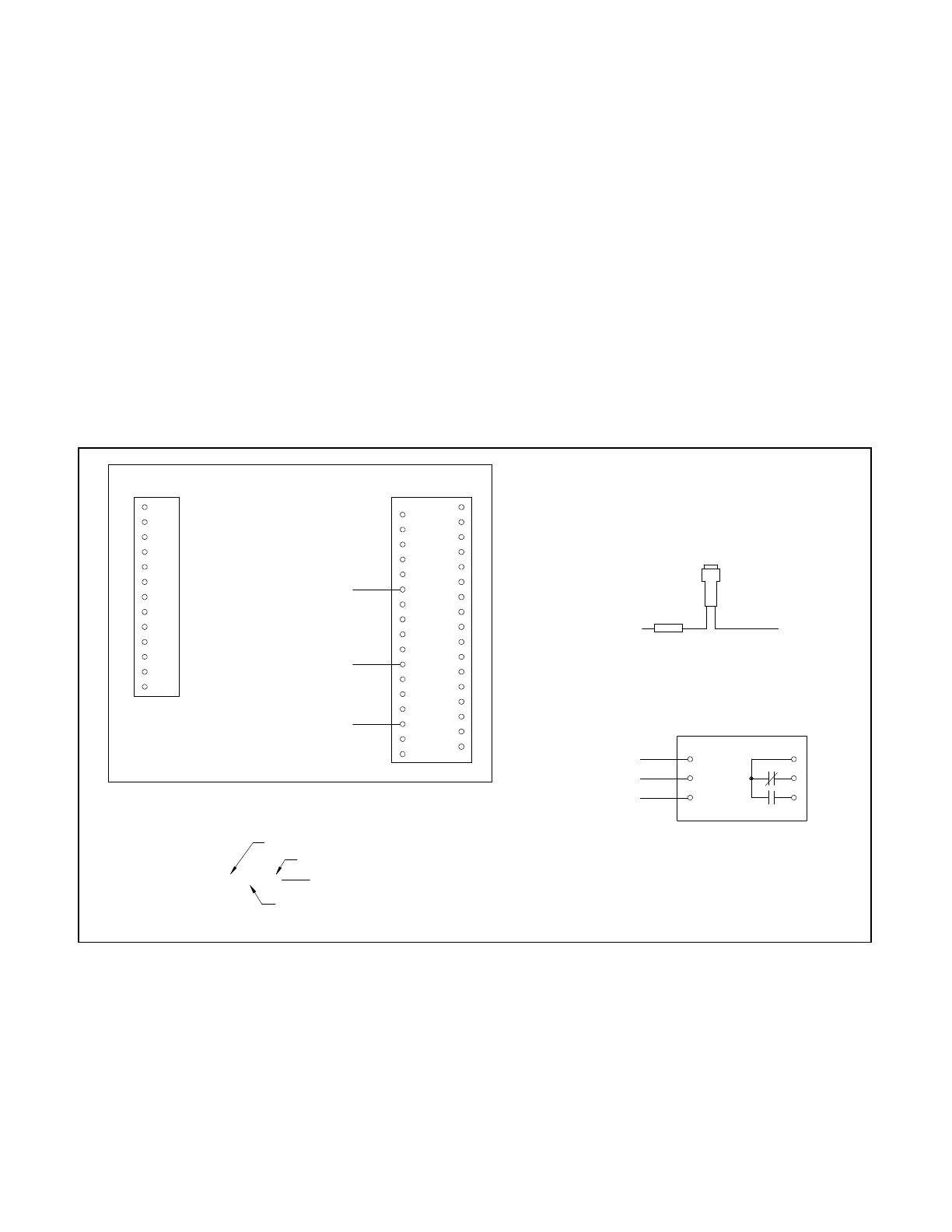
D DD-14-H. Single-contactkitforremoteindication.
This option is rated for 10 amps and for 120 volts
AC. It is used to indicate the normal contactor
position.
D DD-14-J. Single-contact kit for remote indication.
This option is rated for 10 amps and for 120 volts
AC. It is used to indicate the emergency contactor
position.
D DD-14-K. Single-contact kitfor remoteindication.
This option is rated for 10 amps and for 120 volts
AC. It is used to indicate normal source availability.
D DD-14-L. Single-contact kit for remoteindication.
This option is rated for 10 amps and for 120 volts
AC. It is used to indicate emergency source
availability.
D DD-14-M. Single-contactkitforremoteindication.
This option is rated for 10 amps and for 120 volts
AC. It is used to indicate whether the
Automatic/Manual selector switch is not in the
Automatic position.
D DD-14-N. Single-contactkitforremoteindication.
This option is rated for 10 amps and for 120 volts
AC. It is used to indicate whether the programming
mode switch is not in the Off position.
D DD-14-P. Single-contact kit for remoteindication.
This option is rated for 10 amps and for 120 volts
AC. It is used to indicate a system alert condition.
D DD-14-R. Single-contactkitforremoteindication.
This option is rated for 10 amps and for 120 volts
AC. It is used for load bank control. Relay
energizes when the plant exersier is active andthe
contractor does not transfer.
Contacts Shown De-energized
2FU--R--306
TB--DC1--32--132
TB--DC1--28--128
42A
2
K1
DCK
K1
NO
NC
C
306--DCK--42A
BK R
2FU
SPLICE
TB--DC1--23--123
DCK--2--132
DCK--K1--128
2FU--BK--123
TB--DC1
MICROCONTROLLER
TB--AC1
ECS
EAS
NCS
NAS
LC
LB
LA
EC
EB
EA
NC
NB
NA
34
33
32
31
30
29
28
27
26
25
24
23
22
21
20
19
18
16
15
14
13
12
11
10
9
8
7
6
5
4
3
2
1
17
Wire Code Example
S10--13—201
Device Name
Wire Number
Device Terminal
Number
5604522
Figure 5-17. Wiring Diagram—Option DD-14-H, Auxiliary dry contacts