Operation 2-1TP-5672 11/95
Section 2. Operation
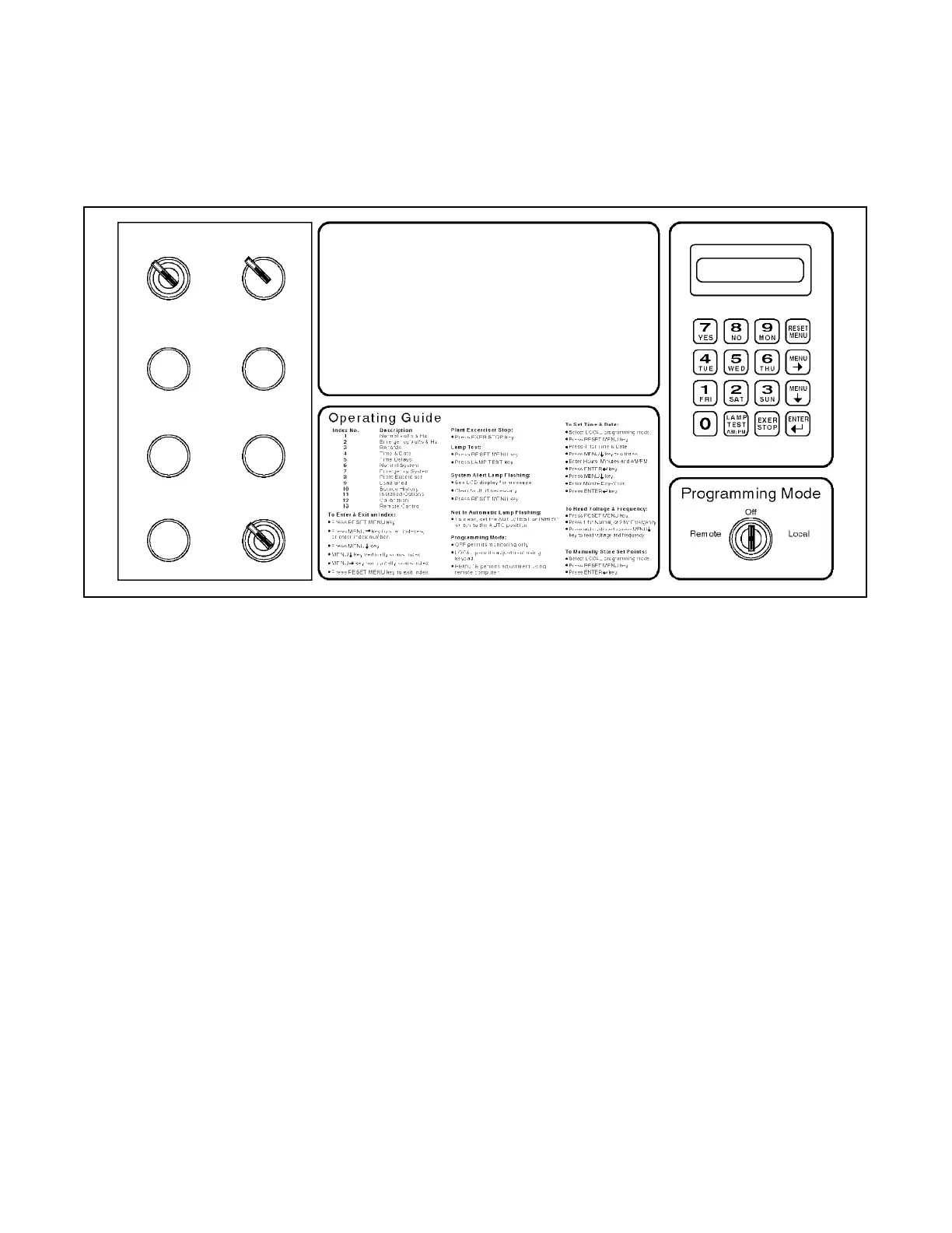
Control Switches and Indicators
Various optional control switches and indicator lamps
may be present on the transfer switch door depending
on the options chosen. See Figure 2-1 for LED, Switch,
and Key locations.
Contactor Position Time Delays
Source Available
System Status
Accessory Active
·
Plant Exerciser Load Shed Inphase Monitor Area Protection
Normal On EndEmergency
Engine Start
Normal To Emergency
Emergency To Normal
Engine Cooldown
Off Position
Normal Emergency
Not In Automatic
Programming Mode Not in Off
Flashing, Local Steady, Remote
·
· ·
·
·
·
·
·
·
·
·
·
·
System Alert
· ·
Off
·
·
· · · ·
· ·
TEST SWITCH
NORMAL TEST
MANUAL
TRANSFER TO
NORMAL
AUTO
TRANSFER
MANUAL
TRANSFER
MANUAL
TRANSFER TO
EMERGENCY
BYPASS
EMERGENCY TO
NORMAL TIME DELAY
MANUAL
TRANSFER TO
OFF
BYPASS NORMAL
TO EMERGENCY
TIME DELAY
AUTO INHIBIT
Figure 2-1. Front Panel
LED Indicators
Contactor Position. LEDs indicate transfer switch
position—NORMAL (green), EMERGENCY (red), or
OFF (yellow).
Source Available. LEDs indicate source with
acceptable voltage and frequency—Normal (green)
and/or Emergency (red).
System Status
Not in Automatic (red). LED flashes to indicate that
Test switch is actuated, or Auto/Manual switch is in the
Manual position.
System Alert (red). LED flashes to indicate possible
problem with contactor or logic operation. System alert
will also flash if any fault signals are received from the
generator set.
Programming Mode Not in Off (yellow). LED flashes
to indicate that programming switch is in the LOCAL
position. A steady, nonflashing light indicates that the
programming switch is in the REMOTE position.