B-4 Appendices
TP-5672 11/95
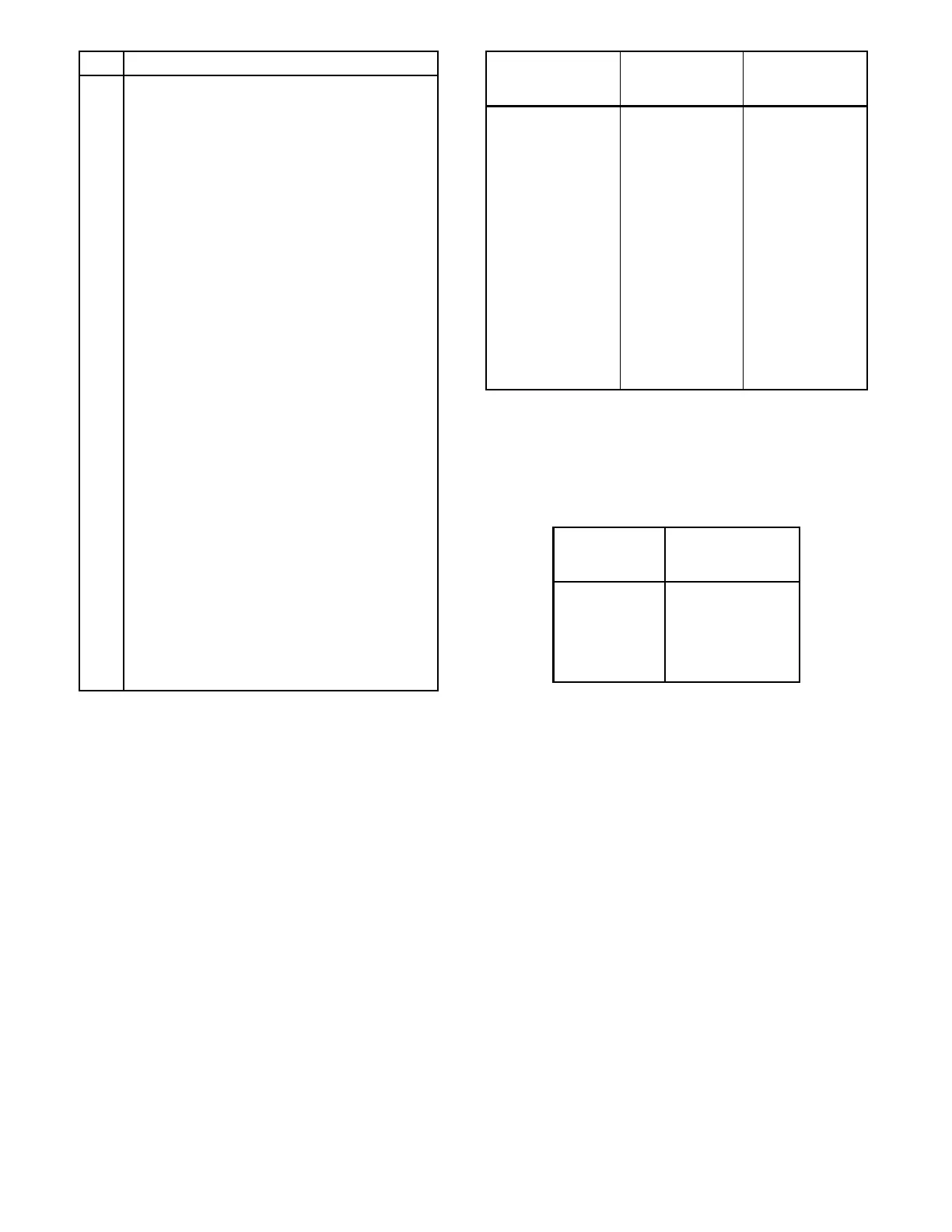
Pin P1-J1 Contactor-transformer Pin Names
1 Normal Phase B.
2 Normal Phase C.
3 N/A
4 Normal contactor position auxiliary contact
common.
5 Normal Phase A.
6 N/A
7 N/A
8 Emergency contactor position auxiliary contact
common.
9 N/A
10 N/A
11 Engine start contact 3.
12 Normal contactor position auxiliary contact
normally open.
13 Emergency Phase C.
14 N/A
15 Engine start contact 4
16 Emergency contactor position auxiliary contact
normally open.
17 Emergency Phase B for sensing.
18 N/A
19 N/A
20 N/A
21 Emergency Phase A
22 N/A
23 Load Phase A
24 Load Phase C
Figure B-3. P1-J1 contactor to power supply board
harness pin numbers and pin names
Trip Point
Setting
Limits
Emergency
Source Factory
Settings
Overvoltage
Dropout 115%-135% 115%
Overvoltage
Pickup 110%-130% 110%
Undervoltage
Pickup 75%-100% 90%
Undervoltage
Dropout 70%-95% 85%
Overfrequency
Dropout 105%-135% 115%
Overfrequency
Pickup 100%-130% 110%
Underfrequency
Pickup 85%-100% 90%
Underfrequency
Dropout 80%-95% 85%
Figure B-4. Emergency source voltage trip point
setting limits and factory settings
Line Voltage
(Volts)
1/25 Of Line
Voltage
(Volts)
120 4.8
208 8.3
240 9.6
480 19.2
600 24.0
Figure B-5. 1/25 of the line voltage