KT-70E / KT-90E / KT-70SE User Manual Page 26 of 59 24 April 2018
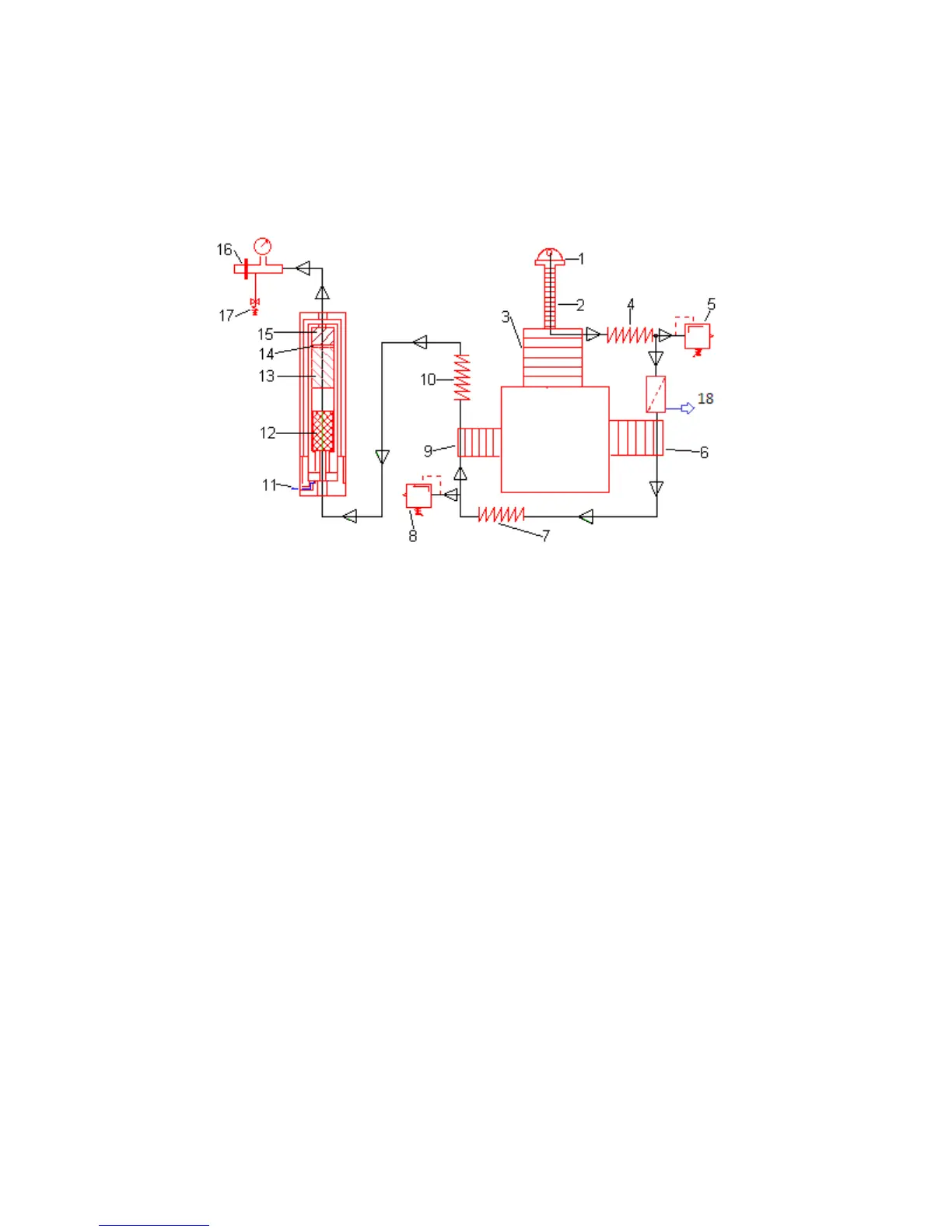
5.5. Pneumatic Flow Diagram – Base Configuration
1. Air Intake Filter
2. Air Intake Hose
3. 1st Compressor Stage
4. Intercooler
5. 1st Stage Pressure Relief Valve
6. 2nd Compressor Stage
7. Intercooler
8. 2nd Stage Pressure Relief Valve
9. 3rd Compressor Stage
10. Aftercooler
11. Condensation Discharge
12. Condensation Absorber
13. Active Coal Granulate
14. Felt Disk
15. Moisture Absorption Granulate
16. Filling Armature
17. Safety Valve
18. Intermediate Condensate Collector and Drain